
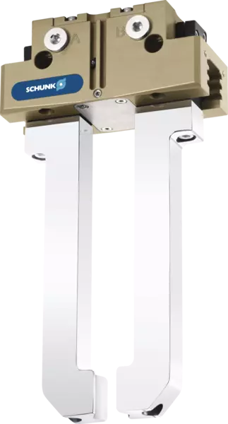
PGN-plus-P
Function
Funktionsschnittbild
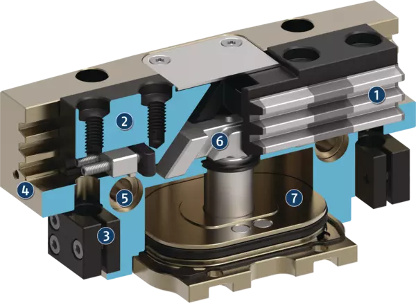
Funktionsschnittbild
Der Kolben wird über Druckluft nach oben bzw. unten bewegt.
Die schrägen Wirkflächen des Keilhakens erzeugen dabei eine synchrone parallele Backenbewegung.
- 1
-
Vielzahn-Gleitführung
Höchste Lebensdauer durch Schmierstofftaschen in der robusten Vielzahnführung sowie Aufnahme hoher Kräfte und Momente über große Führungsabstützung - 2
-
Grundbacke
mit standardisiertem Anschraubbild zur Adaption der werkstückspezifischen Greiferfinger - 3
-
Halterung für Sensorik
Halterungen für Näherungsschalter und einstellbare Schaltnocken im Gehäuse - 4
-
Gehäuse
ist gewichtsoptimiert durch Verwendung einer hochfesten Aluminiumlegierung - 5
-
Zentrier- und Befestigungsmöglichkeiten
für die universelle Montage des Greifers - 6
-
Keilhakenprinzip
für hohe Kraftübertragung und niedrigsten Verschleiß durch größere Schrägzugfläche - 7
-
Kolben
Maximale Kraft durch maximale Fläche des Antriebkolbens
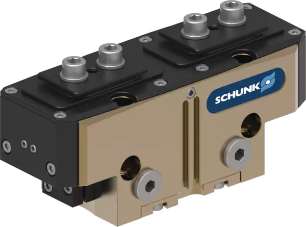
Staubdicht-Version SD
Greifkrafterhaltungs-Version AS/IS
Nastavení spínacích vaček při dotazu s indukčními bezdotykovými spínači

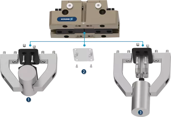
Možnost volitelného připevnění pod krycím plechem pro zakázkovou dodatečnou nástavbu
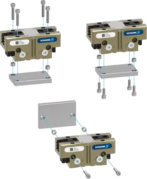
Centering and mounting options for gripper assembly
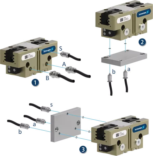
Pneumatic connections for the power supply
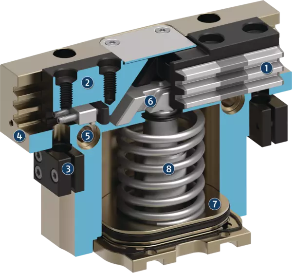
Sectional diagram of gripping force maintenance version AS
Staubdicht-Version SD
Die Option „Staubdicht“ erhöht den Schutzgrad gegen eindringende Stoffe.
Diese kann wahlweise als fertig montierte Greifervariante bestellt werden, oder über den Nachrüstsatz „SAD PGN-plus-P“ auch nachträglich am Greifer nachgerüstet werden.
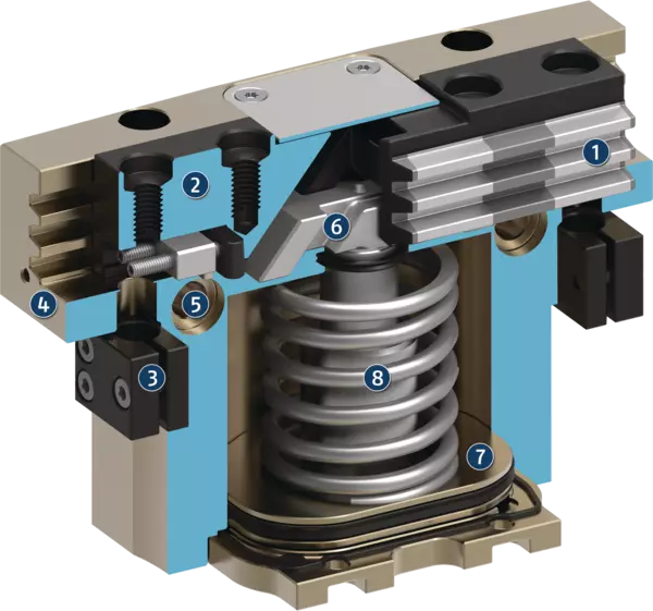
Greifkrafterhaltungs-Version AS/IS
Die mechanische Greifkrafterhaltung stellt auch bei Druckabfall eine Mindestgreifkraft sicher. Diese wirkt bei der AS-Variante als Schließkraft und bei der IS-Variante als Öffnungskraft. Das Bild zeigt die AS-Variante. Die Greifkrafterhaltung lässt sich auch als Greifkrafterhöhung oder für einfach wirkendes Greifen nutzen.
- 1
-
Vícezubé vedení
- 2
-
Základní čelist
- 3
-
Držáky pro snímače
- 4
-
Tělo
- 5
-
Středicí a montážní možnosti
- 6
-
Princip klínového háku
- 7
-
Píst
- 8
-
Zařízení udržující upínací sílu i v případě výpadku médií
Nastavení spínacích vaček při dotazu s indukčními bezdotykovými spínači
Monitorování pomocí indukčních polohových senzorů lze provést jako standard od velikosti 64. Ve stavu dodání jsou polohy "chapadlo otevřeno" a "chapadlo zavřeno" přednastaveny ovládacími vačkami. Indukční senzory musí být objednány samostatně a jsou zasunuty do krytu až po zarážku a upnuty.
S cílem monitorovat jakoukoliv další polohu, např. "obrobek je upnut", je možné obě řídící vačky individuálně nastavit v příslušných základních čelistech.
- 1
-
Řídící vačka je přednastavena do polohy "chapadlo uzavřeno"
- 2
-
Řídící vačka je přednastavena do polohy "chapadlo otevřeno"
- 3
-
Upínač pro upínací šroub k upevnění čidla
- 4
-
Upínací šroub pro procesně spolehlivé upevnění nastaveného spínacího bodu
- 5
-
Seřizovací šroub pro nastavení spínacího bodu
Možnost volitelného připevnění pod krycím plechem pro zakázkovou dodatečnou nástavbu
Chapadlo je dodáváno s namontovaným krycím plechem. Ten je možné v případě potřeby odstranit. Pod krycím plechem se nacházejí závity a upevnění pro montáž zakázkových konstrukcí k zavedení dodatečných funkcí.
- 1
-
Přídavné středění nebo podpěra obrobku
- 2
-
Krycí plech (lze odstranit)
- 3
-
Ejektor s vnějším válcem připevněným k chapadlu
Centering and mounting options for gripper assembly
The gripper can be installed on two sides and in three screw directions. This allows universal and flexible mounting of the gripper in all conceivable arrangements.
Pneumatic connections for the power supply
The gripper can be flexibly supplied with compressed air on three sides.
- 1
-
At the front via the main air connections A and B by means of air connections and pneumatic hoses. Air purge can be optionally created via S.
- 2
-
At the bottom via direct connections a and b by means of hose-free direct connection. The pneumatic supply is then provided via the adapter plate.
- 3
-
At the rear side via direct connections a and b by means of hose-free direct connection. The pneumatic supply is then via the adapter plate. Air purge can be optionally created via s.
Sectional diagram of gripping force maintenance version AS
- 1
-
Multi-tooth guidance
Maximum service life due to lubricant pockets in the robust multi-tooth guidance, and absorption of high forces and torques by means of the large guidance support - 2
-
Base jaw
with standardized screw connection diagram for the connection of the workpiece-specific gripper fingers - 3
-
Bracket for sensors
Brackets for proximity switches and adjustable control cams in the housing - 4
-
Housing
is weight-optimized due to the use of high-strength aluminum alloy - 5
-
Centering and mounting possibilities
for universal assembly of the gripper - 6
-
Wedge-hook design
for high power transmission and minimal wear as a result of larger diagonal pull surfaces - 7
-
Piston
Maximum force through maximum surface of drive piston - 8
-
Gripping force maintenance
The mechanical gripping force maintenance device ensures that a minimum clamping force will be applied even if there is a drop in pressure.
Application example
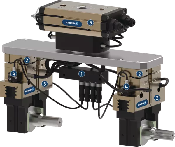
Application example
Handling tool for loading and unloading raw and finished parts and compensation of inaccurate position. A sensor distributor is used for routing signals through a cable.
- 1
-
Sensor distributor V4
- 2
-
Tolerance compensation unit TCU-Z
- 3
-
Universal gripper PGN-plus-P
- 4
-
IN sensors
- 5
-
Universal rotary actuator SRM