
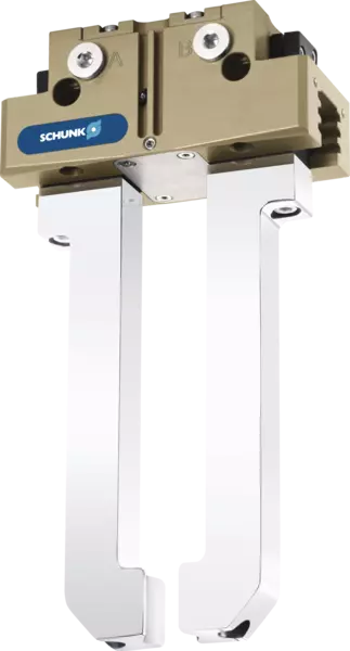
PGN-plus-P
Functie
Sectional diagram
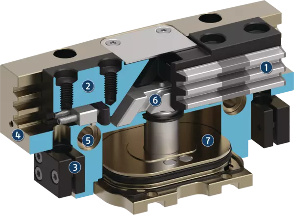
Sectional diagram
The piston is moved up and down by compressed air.
The angled active surfaces of the wedge-hook produce a synchronized, parallel jaw motion.
- 1
-
Multi-tooth guidance
Maximum service life due to lubricant pockets in the robust multi-tooth guidance, and absorption of high forces and torques by means of the large guidance support - 2
-
Base jaw
with standardized screw connection diagram for the connection of the workpiece-specific gripper fingers - 3
-
Bracket for sensors
Brackets for proximity switches and adjustable control cams in the housing - 4
-
Housing
is weight-optimized due to the use of high-strength aluminum alloy - 5
-
Centering and mounting possibilities
for universal assembly of the gripper - 6
-
Wedge-hook design
for high power transmission and minimal wear as a result of larger diagonal pull surfaces - 7
-
Piston
Maximum force through maximum surface of drive piston
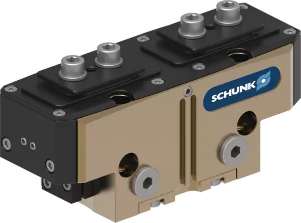
ATEX-versie EX
Variant voor behoud van grijpkracht AS/IS
Impostazioni delle camme di controllo durante il monitoraggio con interruttori di prossimità induttivi

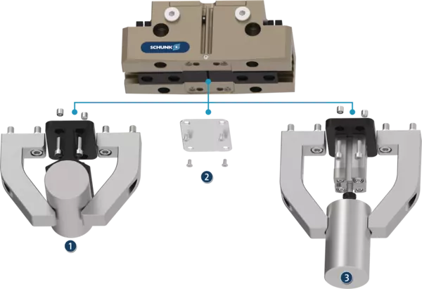
Optional mounting possibility under the cover sheet for customer-specific additional structure
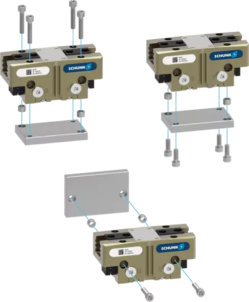
Centreer- en montagemogelijkheden voor grijpermontage
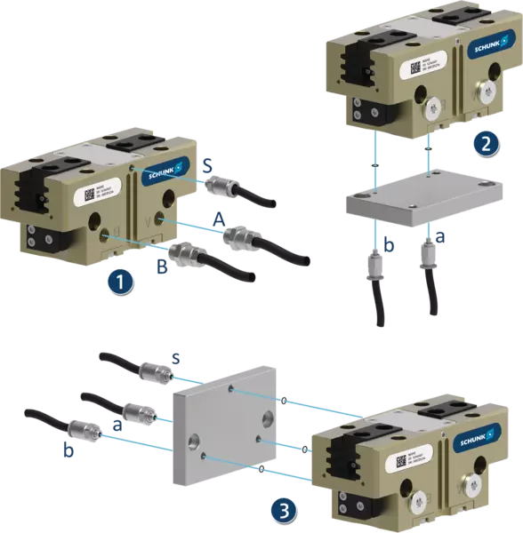
Pneumatische aansluitingen voor de stroomvoorziening
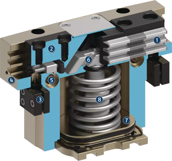
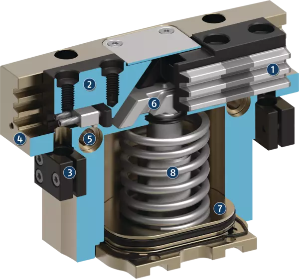
Doorsnedeschema voor behoud van grijpkracht AS
ATEX-versie EX
De 'stofdichte' optie biedt een betere bescherming tegen binnendringende stoffen.
U kunt de optie naar keuze bestellen als kant-en-klaar gemonteerde grijpervariant of u kunt ze achteraf op de grijper monteren door het pakket "SAD PGN-plus-P" te bestellen.
Variant voor behoud van grijpkracht AS/IS
Het mechanische toestel voor het behoud van de grijpkracht zorgt ervoor dat zelfs bij een drukval een minimale klemkracht wordt toegepast. In de AS-variant zorgt dit voor sluitkracht en in de IS-variant voor openingskracht. De afbeelding geeft de AS-variant weer. Daarnaast kan het toestel voor het behoud van de grijpkracht worden gebruikt om de grijpkracht te verhogen of voor grijpen in één richting.
- 1
-
Guida di scorrimento dentata
- 2
-
Griffa
- 3
-
Staffa per sensori
- 4
-
Corpo
- 5
-
Possibilità di centraggio e montaggio
- 6
-
Sistema a piani inclinati
- 7
-
Pistoni
- 8
-
Dispositivo di mantenimento della forza di presa
Impostazioni delle camme di controllo durante il monitoraggio con interruttori di prossimità induttivi
Il monitoraggio con interruttore di prossimità induttivo può essere eseguito di serie dalla dimensione 64. Al momento della consegna, le posizioni "pinza aperta" e "pinza chiusa" sono preimpostate con le camme di controllo. I sensori induttivi devono essere ordinati separatamente, vengono fatti scorrere all'interno della custodia fino all'arresto e serrati.
Per monitorare altre posizioni, ad esempio "pezzo serrato", entrambe le camme di controllo possono essere impostate singolarmente nelle rispettive ganasce di base.
- 1
-
Control cam preset for "gripper closed" position
- 2
-
Control cam preset for "gripper open" position
- 3
-
Holder with clamping screw for fixing the sensor
- 4
-
Clamping screw for process-reliable fixing of the adjusted switching point
- 5
-
Adjusting screw for setting any switching point
Optional mounting possibility under the cover sheet for customer-specific additional structure
In delivery state, a cover sheet is mounted to the gripper. This can be removed if necessary. Under the cover sheet are threads and fittings for mounting customer-specific designs for implementing additional functions.
- 1
-
Extra centrering of ondersteuning van het werkstuk
- 2
-
De afdekplaat (kan worden verwijderd)
- 3
-
Ejector met externe cilinder bevestigd aan de grijper
Centreer- en montagemogelijkheden voor grijpermontage
De grijper kan aan twee kanten en in drie schroefrichtingen worden geïnstalleerd. Hierdoor is een universele en flexibele montage van de grijper in alle denkbare opstellingen mogelijk.
Pneumatische aansluitingen voor de stroomvoorziening
De grijper kan aan drie zijden flexibel van perslucht worden voorzien.
- 1
-
Aan de voorzijde via de hoofdluchtaansluitingen A en B door middel van luchtaansluitingen en pneumatische slangen. Via S kan optioneel een ontluchting worden gecreëerd.
- 2
-
Onderaan via directe aansluitingen a en b door middel van slangloze directe verbinding. De pneumatische toevoer wordt dan geleverd via de adapterplaat.
- 3
-
Lateraal via directe aansluitingen a en b door middel van slangloze directe verbinding. De pneumatische toevoer gaat dan via de adapterplaat. Via S kan optioneel een ontluchting worden gecreëerd.
Doorsnedeschema voor behoud van grijpkracht AS
- 1
-
Multi-tooth guidance
Maximum service life due to lubricant pockets in the robust multi-tooth guidance, and absorption of high forces and torques by means of the large guidance support - 2
-
Base jaw
with standardized screw connection diagram for the connection of the workpiece-specific gripper fingers - 3
-
Bracket for sensors
Brackets for proximity switches and adjustable control cams in the housing - 4
-
Housing
is weight-optimized due to the use of high-strength aluminum alloy - 5
-
Centering and mounting possibilities
for universal assembly of the gripper - 6
-
Wedge-hook design
for high power transmission and minimal wear as a result of larger diagonal pull surfaces - 7
-
Piston
Maximum force through maximum surface of drive piston - 8
-
Gripping force maintenance
The mechanical gripping force maintenance device ensures that a minimum clamping force will be applied even if there is a drop in pressure.
Application example
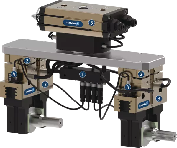
Application example
Handling tool for loading and unloading raw and finished parts and compensation of inaccurate position. A sensor distributor is used for routing signals through a cable.
- 1
-
Sensor distributor V4
- 2
-
Tolerance compensation unit TCU-Z
- 3
-
Universal gripper PGN-plus-P
- 4
-
IN sensors
- 5
-
Universal rotary actuator SRM