
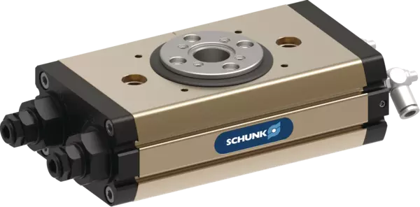
SRM 25-H-180-3-4P-SI
ID 1347277
- Angle of rotation: 180 °
- End position adjustability: 3 °
- End position damping: hydr. damper
- Torque: 4 Nm
- No. of fluid feed-throughs: 4
Technical details
| End position damping | hydr. damper |
|---|---|
| Angle of rotation [°] | 180 |
| Torque [Nm] | 4.0 |
| Number of intermediate positions | none |
| IP protection class | 65 |
| Weight [kg] | 2.78 |
| Fluid consumption (2x nom. angle) [cm³] | 84.0 |
| Nominal operating pressure [bar] | 6.0 |
| Min. operating pressure [bar] | 4.0 |
| Max. operating pressure [bar] | 6.5 |
| Diameter of connecting hose | 6 x 3.9 x 1.05 |
| Min. ambient temperature [°C] | 5.0 |
| Max. ambient temperature [°C] | 60.0 |
| Cleanroom class ISO 14644-1 | 5 |
| Cleanroom class: ISO 14644-1 | 2015 |
| Repeat accuracy [°] | 0.07 |
| Diameter of center bore [mm] | 17.1 |
| Max. permissible mass moment of inertia [kgm²] | 0.5 |
| Moment My max. [Nm] | 64.0 |
| Max. axial force Fz max. [N] | 2250.0 |
| No. of fluid feed-throughs | 4.0 |
| Min. pressure in the fluid feed-through [bar] | -0.8 |
| Max. pressure fluid feed-through [bar] | 8.0 |
| Max. volumetric flow of feed-through (at 6 bar) [l/min] | 140.0 |
| Option for inductive proximity switches | yes |
| Position monitoring is adjustable | yes |
| Version with media feed-through | yes |
| Version for inductive sensors, adjustable | yes |
Dimensionen und max. Belastungen
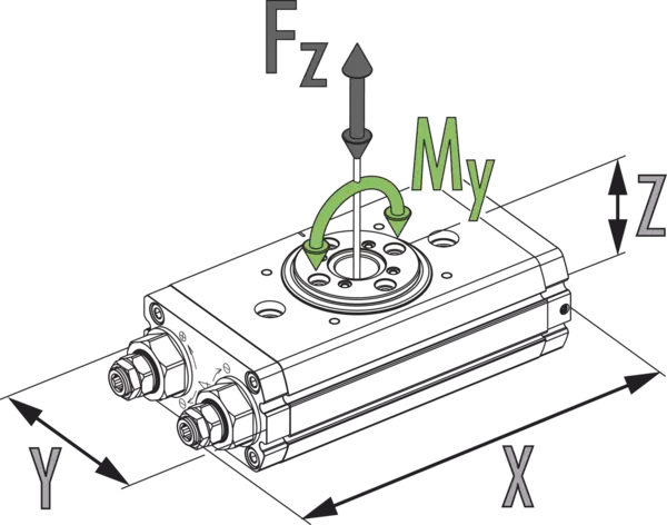
Max. permissible inertia J*

Dimensionen und max. Belastungen
Die angegebenen Momente und Kräfte sind statische Werte, gültig für die Basiseinheit und dürfen gleichzeitig auftreten. Die Drosselung muss immer vorgenommen werden, damit die Drehbewegung schlag- und prellfrei erfolgen kann. Ansonsten kann sich die Lebensdauer verringern.
Max. permissible inertia J*
- X-axis:
- Swiveling time
- Y-axis:
- Mass moment of inertia
- X-axis top:
- Cycles per hour
Informazioni generali sulla serie
Precisione di ripetibilità
È definita come variazione della posizione finale dopo 100 cicli consecutivi.
Posizione del pignone
È sempre contrassegnata nella posizione finale sinistra. Da questo punto il pignone gira verso destra, in senso orario. La freccia indica il senso di rotazione.
Piano di fissaggio sul pignone
Se si imposta un angolo di rotazione inferiore a 90°, la battuta sinistra deve essere completamente ruotata. Questo significa che la posizione finale sinistra ha un piano di fissaggio sul pignone che è ruotato in senso orario di 90° rispetto alla vista principale, la quale evidenzia un angolo di rotazione di 180°.
Angolo di rotazione personalizzato
Altri angoli di rotazione sono disponibili su richiesta.
Coppia nelle posizioni finali
Tenere presente che gli ultimi gradi angolari (ca. 2°) precedenti la posizione finale si possono percorrere solo con la forza di un pistone di azionamento. I moduli a doppia alimentazione dispongono così in questo ambito solo della metà circa della coppia nominale.
Traslazione nella posizione centrale pneumatica
Si esegue solo con il 50% della coppia nominale.
Tempo di rotazione
Si tratta del tempo di rotazione del pignone/della flangia intorno all'angolo di rotazione nominale. I tempi di commutazione delle valvole, i tempi di riempimento dei tubi o i tempi di reazione del PLC non sono compresi in questi valori ma vanno presi in considerazione per determinare i tempi di ciclo.
Condizioni standard
I dati tecnici menzionati si riferiscono a un ambiente di 20 °C e pressione atmosferica.
Materiale del corpo pinza
Alluminio (profilo estruso)
Azionamento
pneumatico, tramite aria compressa filtrata secondo la norma ISO 8573-1:2010 [7:4:4].
Principio di funzionamento
Principio pignone-cremagliera a doppio pistone
La fornitura comprende
Attuatore rotante nella variante ordinata, bustina con pezzi aggiuntivi (bussole di centraggio, O-ring per collegamento diretto/per il contenuto dettagliato vedere le istruzioni per l'uso) e informazioni di sicurezza. Le istruzioni specifiche del prodotto si possono scaricare da schunk.com/downloads-manuals.
Garanzia
24 mesi
Caratteristiche di vita utile
Su richiesta