DDF 2-040-P2-E4
ID 323046
- No. of fluid feed-throughs: 2
- Number of electrical feed-throughs: 4
- Workpiece weight: 10 kg
- Force Fz max.: 400 N
- Force Fd max.: 4000 N
Technical details
| Feed-through | pneumatic and electric feed-through |
|---|---|
| Recommended handling weight [kg] | 10.0 |
| Max. drive speed [1/min] | 120.0 |
| Max. speed of rotation [°/s] | 720.0 |
| Nominal torque [Nm] | 1.5 |
| Starting torque [Nm] | 2.0 |
| Angle of rotation [°] | > 360 |
| No. of fluid feed-throughs | 2.0 |
| Air connection thread pneumatic feed-through | 2x M5 |
| Max. pressure per connection [bar] | 10.0 |
| Rate of flow at 6 bar (per channel) [l/min] | 200.0 |
| Max. air pressure air purge [bar] | 1.0 |
| Number of electrical feed-throughs | 4.0 |
| Max. voltage [V] | 60.0 |
| Max. current strength [A] | 1.0 |
| Weight [kg] | 0.9 |
| Robot-side connection | ISO 9409-1-40-4-M6 |
| Min. ambient temperature [°C] | 5.0 |
| Max. ambient temperature [°C] | 60.0 |
| Max. dynamic bending moment Mx* [Nm] | 25.0 |
| Max. dynamic bending moment My* [Nm] | 25.0 |
| Max. dynamic torsional moment Mz* [Nm] | 20.0 |
| Max. shear force Fq* [N] | 100.0 |
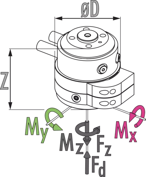
| Diameter D [mm] | 78.0 |
| Height Z [mm] | 62.0 |
| Bending moment Mx [Nm] | 75.0 |
| Bending moment My [Nm] | 75.0 |
| Force Fz max. [N] | 400.0 |
| Max. force Fd [N] | 4000.0 |
A version for vacuum feed-through is available on request. Please ask for details.
Dimensions and maximum loads


Dimensions and maximum loads
Static forces and moments which may act on the rotary feed-through
General notes about the series
Harsh environmental conditions
Please note that use under harsh environmental conditions (e.g. in the coolant area, cast and grinding dust) can considerably reduce the service life of the units, and we will not take over any warranty. However, in many cases we can find a solution. Please contact us for assistance.
Handling weight
is the weight of the total load attached to the flange. When designing, the permissible forces and moments have to be paid attention to. Please note that exceeding the recommended handling weight will shorten the lifespan.
Mounting
Standardized ISO 9409 interface (robot-side)
Housing
high-strength, hard-coated aluminum alloy
Scope of delivery
Rotary feed-through in the ordered variant, elements for mechanical connection and safety information. Product-specific instructions can be downloaded at schunk.com/downloads-manuals.
Warranty
24 months

