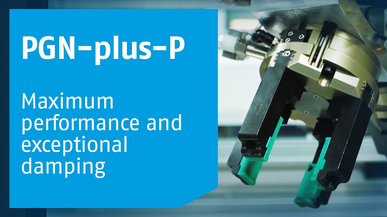
PGN-plus-P: Forever a benchmark
The industry leader in each of its values – The PGN-plus-P demonstrates proof of performance

Many insights. A success story.


The No. 1 for more than 30 years
The SCHUNK universal gripper PGN-plus-P is the most proven and versatile gripper on the market.
One of a kind! The patented SCHUNK multi-tooth guidance
The multi-tooth guidance of the SCHUNK grippers PGN-plus-P and PGN-plus-E has been further perfected with the permanent lubrication and sets the technological benchmark for this gripper class. The current universal grippers PGN-plus-P and PGN-plus-E are the products of over 30 years of SCHUNK experience.

PGN-plus-P with multi-tooth guidance and permanent lubrication
We have improved the tried and tested technology even further in the universal gripper PGN-plus-P. For multi-tooth guidance, the supporting dimension between the six load-bearing shoulders was increased by up to 40%, thereby increasing the size of the guiding areas.
The benefits at a glance:
- Up to 120% higher finger load is possible*
- Up to 50% longer gripper fingers possible*
- Increased performance at the same gripper size and higher performance from the system
- Rapid and even lubricant distribution even with short strokes
* compared to a T-slot guidance

Technology makes all the difference!

The technology of the new SCHUNK PGN-plus-P gripper has more to offer! With its powerful features, the PGN-plus-P is in a class of its own.
Profit from the benefits:
- Rapid and even lubricant distribution
even with short strokes - Reduced total cost of ownership (TCO)
- Permanently higher performance
- More compact, efficient systems
- Continuously reliable and robust
PGN-plus-P technology in detail
The SCHUNK gripper PGN-plus-P raises the bar even further for pneumatically actuated universal grippers. The optimized multi-tooth guidance with permanent lubrication sets a benchmark on the market. At the same time, the PGN-plus-P benefits from the unique range of SCHUNK accessories for virtually the entire range of all conceivable automated applications.
- Up to 50% longer gripper fingers
The improved multi-tooth guidance enables the use of even longer gripper fingers for the same gripper size due to higher maximum moments, without overloading the guidance. Gripping with optimized interfering contours during handling tasks in confined spaces, is thereby made even easier.

- Longest service life due to lubrication pockets in the multi-tooth guidance
The lubricant pockets in the multi-tooth guidance ensure a continuous grease supply. The advantage is an even lubricant film that is created rapidly, even with short strokes.
- Up to 50% higher gripping force
The enlarged surface of the drive piston in the compact installation space of the PGN-plus-P allows an increase of the gripping force. Heavier workpiece weights can be handled with the same gripper size.

- Up to 120% higher finger load is possible
For multi-tooth guidance with permanent lubrication, the supporting dimension between the six load-bearing shoulders was increased, thereby increasing the size of the guiding areas.


Sensor system
Unique variety of sensor systems e.g. magnetic switch MMS, inductive proximity switch IN, and much more.
PGN-plus-P suitable for any application!
Versions
- Gripping force maintenance version AS/IS
The mechanical gripping force maintenance version ensures minimum gripping force even in the event of a pressure drop. In the AS/IS variant this acts as a closing force, in the IS variant as an opening force - Corrosion-protected version K
for use in corrosion-inducing atmospheres - High-temperature version V/HT
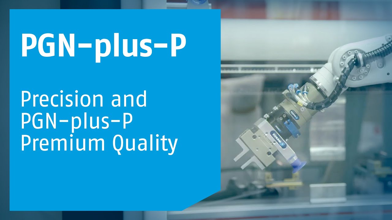
for use in hot environments - Precision version P
for the highest accuracy - ATEX version EX
for explosive environments - Dustproof version SD
absolutely dustproof, increased degree of protection against ingress of materials. - Application-specific protective covers
up to protection class IP67, for use in high-temperature ranges - Additional versions
Various options can be combined - Food-compliant lubrication
The product contains food-compliant lubricants as standard. The requirements of EN 1672-2:2020 are not fully met. The corresponding NSF certificates can be found at https://info.nsf.org/USDA/Listings.asp can be called up with help of the lubricant information in the operating manual.

The differences at a glance
PGN-plus-P
- Universal application possibilities
- 10% longer gripper fingers with the same size
- More than 2,000 possible combinations of variants and options

JGP-P
- For cost-sensitive applications
- Ten sensor systems for variable monitoring options
Photo gallery