For existing customers, SCHUNK offers the CMS manual change system as a 1:1 replacement for the predecessor model. It complements the proven attributes of the predecessor model with new functions.
CMS
Manual change system
User-friendly manual change system with extensive complementary portfolio

Flexible. Compact. Intuitive.
Manual change system CMS
It pays off to change over
With its user-friendliness, diversity of modules, and extensive range of accessories, the CMS manual change system is highly impressive . It can be used on robots as well as in stationary applications, wherever tool changes are important.
Take advantage of the benefits
- Increased process reliability
By means of integrated locking and tool presence monitoring in all sizes (sensors optional)
- Integrated air feed-throughs
All feed-throughs can be used radially and axially for pneumatics and vacuum.
Basic variant available without integrated feed-through
- Direct screw mounting of electrical, pneumatic and fluid modules
Enables versatile energy transmission for controlling a wide range of tools
- Food-grade lubrication
The product contains food-compliant lubricants as standard. The requirements of EN 1672-2:2020 are not fully met. The corresponding NSF certificates can be found at https://info.nsf.org/USDA/Listings.asp can be called up with the help of the lubricant details in the operating manual.
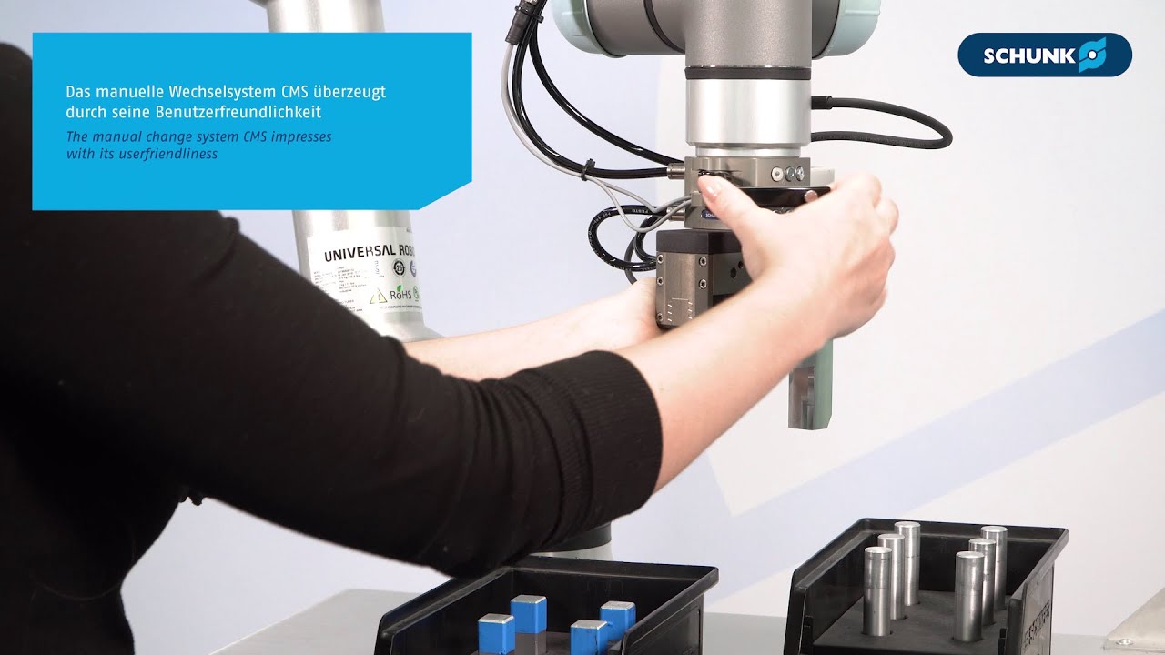
CMS in use


Manual tool change
The application video shows how quickly and easily tools can be changed with the CMS change system. The mechatronic gripper EGU and the pneumatic gripper PGL-plus-P are replaced. The high diversity of modules for the change system offers a wide range of media transmission options