

SRU-plus 50-H-90-3-8-M8-AS
ID 362707
- No. of fluid feed-throughs: 8
- Size of the E-connections on the output end: M8
- Torque: 50.3 Nm
Technical details
| Tlumení koncové polohy | hydr. tlumič |
|---|---|
| Úhel rotace [°] | 90 |
| Nastavitelnost koncové polohy [°] | 3 |
| Krouticí moment [Nm] | 50.3 |
| Počet mezi poloh | žádné |
| Třída ochrany IP | 67 |
| Vlastní hmotnost [kg] | 11.55 |
| Spotřeba kapaliny (2 x jmenovitý úhel) [cm³] | 448.0 |
| Jmenovitý provozní tlak [bar] | 6.0 |
| Min. provozní tlak [bar] | 4.0 |
| Max. provozní tlak [bar] | 8.0 |
| Průměr připojovací hadice | 8 x 6 x 1 |
| Min. okolní teplota [°C] | 5.0 |
| Max. okolní teplota [°C] | 60.0 |
| Opakovatelná přesnost [°] | 0.05 |
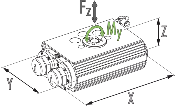
| Délka X [mm] | 317.0 |
| Šířka Y [mm] | 150.0 |
| Výška Z [mm] | 173.0 |
| Max. moment My [Nm] | 340.0 |
| Max. axiální síla Fz max. [N] | 9000.0 |
| Verze s tvrdým tlumičem | ano |
| Verze s přívodem kapaliny | ano |
| Počet průchodů médií | 8.0 |
| Max. tlak v kapalinovém přívodu [bar] | 8.0 |
| Verze s elektrickými průchody | ano |
| Počet vodičů | 10.0 |
| Max. napětí [V] | 24.0 |
| Max. proud vodičem [A] | 1.0 |
| Max. celkový proud [A] | 1.0 |
| Verze s montážní sadou | ano |
| Čistota místnosti třída ISO 14644-1 | 5 |
| Stav certifikace Třída čistého prostoru ISO 14644-1 | 1999 |
Rozměry a maximální zatížení
Max. přípustná setrvačnost J*

Max. přípustná setrvačnost J*

Rozměry a maximální zatížení
Uvedené momenty a síly jsou statické hodnoty a mohou se objevovat současně. Škrcení vstupního vzduchu je nutné k zajištění toho, aby jednotka dokázala najet do koncových poloh bez rázů. Jinak se snižuje životnost.
Max. přípustná setrvačnost J*
- X-axis:
- Doba otáčení
- Y-axis:
- Hmotnostní moment setrvačnosti
- X-axis top:
- Cykly za hodinu
Max. přípustná setrvačnost J*
- X-axis:
- Doba otáčení
- Y-axis:
- Hmotnostní moment setrvačnosti
- X-axis top:
- Cykly za hodinu
Allgemeine Hinweise zur Baureihe
Wiederholgenauigkeit
ist definiert als Streuung der Endlage bei 100 aufeinanderfolgenden Schwenkzyklen.
Ritzelposition
ist stets in der linken Endlage gezeichnet. Von hier aus dreht das Ritzel nach rechts im Uhrzeigersinn. Der Pfeil verdeutlicht die Drehrichtung.
Anschraubbild am Ritzel
Bei der Einstellung eines Schwenkwinkels kleiner 90° muss der linke Endanschlag komplett hineingedreht werden. Dadurch besitzt die linke Endlage ein um 90° im Uhrzeigersinn gedrehtes Anschraubbild am Ritzel im Vergleich zur Hauptansicht, die den Zustand bei einem Schwenkwinkel von 180° zeigt.
Kundenspezifische Schwenkwinkel
Für diese Einheit sind weitere Schwenkwinkel auf Anfrage erhältlich.
Drehmoment in Endlagen
Bitte beachten Sie, dass die letzten Winkelgrade (ca. 2°) vor der Endlage nur mit der Kraft eines Antriebskolbens gefahren wird. Somit haben doppelt beaufschlagte Module in diesem Bereich nur etwa die Hälfte des Nenndrehmomentes zur Verfügung. Durch einen externen Anschlag kann auch in den Endlagen für das volle Drehmoment gesorgt werden.
Fahrt in pneumatische Mittelstellung
wird nur mit dem halben Nenndrehmoment durchgeführt.
Schwenkzeit
ist die reine Rotationszeit des Ritzels/Flansches um den Nenndrehwinkel. Ventilschaltzeiten, Schlauchbefüllungszeiten oder SPS-Reaktionszeiten sind nicht enthalten und bei der Ermittlung von Zykluszeiten zu berücksichtigen.
Standard conditions
The technical data shown refers to an environment of 20 °C and atmospheric pressure.
Housing material
Aluminum (extruded profile)
Actuation
pneumatic, with filtered compressed air as per ISO 8573-1:2010 [7:4:4].
Operating principle
Double piston rack and pinion principle
Scope of delivery
Flow control valves, centering bushings, O-rings for direct connection, fitting screws (SRU-plus 63 only), assembly and operating manual with manufacturer’s declaration
Warranty
24 months
Service life characteristics
on request