
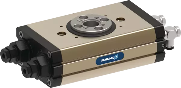
SRM 32-H-180-90-M-SI
ID 1500689
- Angle of rotation: 180 °
- End position adjustability: 90 °
- End position damping: hydr. damper
- Torque: 12 Nm
Technical details
| End position damping | hydr. damper |
|---|---|
| Angle of rotation [°] | 180 |
| Torque [Nm] | 12.0 |
| Torque center position [Nm] | 7.0 |
| Number of intermediate positions | 1 x M (pneumatic) |
| IP protection class | 65 |
| Weight [kg] | 4.47 |
| Fluid consumption (2x nom. angle) [cm³] | 195.0 |
| Nominal operating pressure [bar] | 6.0 |
| Min. operating pressure [bar] | 4.0 |
| Max. operating pressure [bar] | 6.5 |
| Diameter of connecting hose | 6 x 3.9 x 1.05 |
| Min. ambient temperature [°C] | 5.0 |
| Max. ambient temperature [°C] | 60.0 |
| Cleanroom class ISO 14644-1 | 5 |
| Cleanroom class: ISO 14644-1 | 2015 |
| Repeat accuracy [°] | 0.05 |
| Diameter of center bore [mm] | 21.1 |
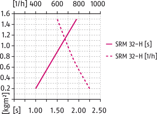
| Max. permissible mass moment of inertia [kgm²] | 0.4 |
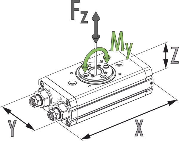
| Moment My max. [Nm] | 91.0 |
| Max. axial force Fz max. [N] | 2750.0 |
| Option for inductive proximity switches | yes |
| Position monitoring is adjustable | yes |
| Version for inductive sensors, adjustable | yes |
Dimensions and maximum loads
Max. permissible inertia J*
Dimensions and maximum loads
The indicated moments and forces are static values, valid for the base unit, and may appear simultaneously. Throttling has to be done for ensuring that the rotary movement takes place without impact or bouncing. Otherwise the service life reduces.
Max. permissible inertia J*
- X-axis:
- Swiveling time
- Y-axis:
- Inertia
- X-axis top:
- Cycles per hour
General notes about the series
Repeat accuracy
is defined as a distribution of the end position for 100 consecutive cycles.
Pinion position
is always shown in the left end position. The pinion rotates from here to the right in clockwise direction. The arrow makes the direction of rotation clear.
Pinion screw connection diagram
When setting a swivel angle smaller than 90°, the left end stop must be completely turned in. This means that the left end position has a screw connection diagram on the pinion which is clockwise turned by 90° compared to the main view, which shows a swivel angle of 180°.
Customized angle of rotation
More swivel angles are available on request.
Torque in the end positions
Please note that the final angular degrees (approx. 2°) before the end position can only be approached using the force of a single drive piston. For this reason, double actuated modules only have about half the rated torque available in this area.
Travel to the pneumatic middle position
is carried out using only half of the nominal torque.
Swiveling time
is the rotation time of pinion/flange around the nominal rotation angle. Valve switching times, hose filling times, or PLC reaction times are not included and are to be considered when cycle times are calculated.
Standard conditions
The technical data shown refers to an environment of 20 °C and atmospheric pressure.
Housing material
Aluminum (extruded profile)
Actuation
pneumatic, with filtered compressed air as per ISO 8573-1:2010 [7:4:4].
Operating principle
Double piston rack and pinion principle
Scope of delivery
Swivel unit in the ordered variant, accessory kit (centering sleeves, O-rings for direction connection/detailed contents see operating manual) and safety information. Product-specific instructions can be downloaded at schunk.com/downloads-manuals.
Warranty
24 months
Service life characteristics
on request