
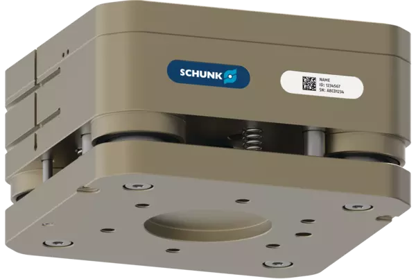
AGM-Z 100
ID 1575979
- Compensation Z: 15 mm
- Force Fz max.: 2100 N
- Force Fd max.: 4200 N
- Max. spring force: 700 N
- IP protection class: 50
Détails techniques
| Compensation Z [mm] | 15.0 |
|---|---|
| Locking force retracted [N] | 2500.0 |
| Locking force extended [N] | 3600.0 |
| Min. spring force [N] | 230.0 |
| Max. spring force [N] | 700.0 |
| Min. operating pressure [bar] | 2.5 |
| Max. operating pressure [bar] | 6.5 |
| Nominal operating pressure [bar] | 6.0 |
| Repeat accuracy [mm] | 0.02 |
| Robot-side connection | ISO 9409-1-100-6-M8 |
| Tool-side connection | ISO 9409-1-100-6-M8 |
| Weight [kg] | 6.0 |
| Min. ambient temperature [°C] | 5.0 |
| Max. ambient temperature [°C] | 60.0 |
| Fluid consumption [cm³] | 190.0 |
| Extension time [s] | 0.4 |
| Retraction time [s] | 0.7 |
| Air connections locked and unlocked | G1/8" |
| Max. eccentric load [mm] | 340.0 |
| IP protection class | 50 |
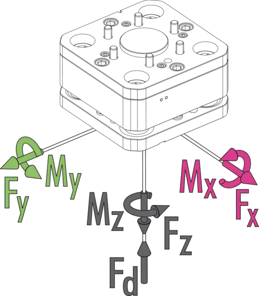
| Max. static moment Mx/My [Nm] | 200.0 |
| Max. static moment Mz [Nm] | 350.0 |
| Max. static force Fx/Fy [N] | 2000.0 |
| Max. static force Fz [N] | 2100.0 |
| Max. dynamic moment Mx/My [Nm] | 90.0 |
| Max. dynamic moment Mz [Nm] | 150.0 |
| Force Fx max. dynamic [N] | 900.0 |
| Force Fy max. dynamic [N] | 900.0 |
| Force Fz max. dynamic [N] | 1050.0 |
| Max. force Fd [N] | 4200.0 |
Max. loads
AGM-Z load diagram – vertical structure

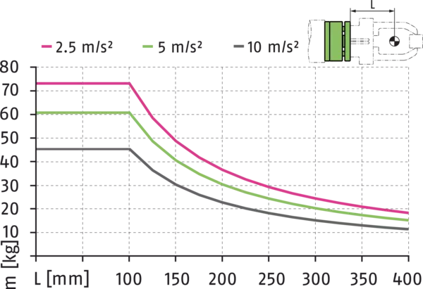
AGM-Z load diagram – horizontal structure
Deflection
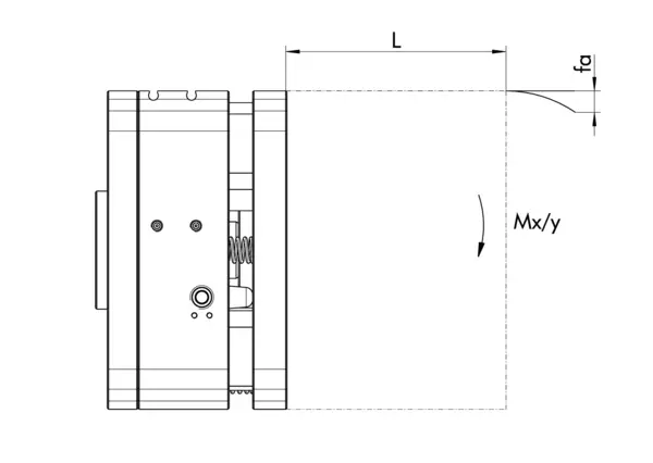
AGM-Z deflection diagram – horizontal structure

Max. loads
This is the sum of all static loads that are permitted to act on the compensation unit.
AGM-Z load diagram – vertical structure
- Axe X:
- Distance of the center of gravity
- Axe Y:
- Load capacity
AGM-Z load diagram – horizontal structure
- Axe X:
- Distance of the center of gravity
- Axe Y:
- Load capacity
Deflection
AGM-Z deflection diagram – horizontal structure
- Axe X:
- Distance of the center of gravity
- Axe Y:
- Deflection
Allgemeine Hinweise zur Baureihe
Extreme Umweltbedingungen
Bitte beachten Sie, dass der Einsatz unter extremen Umweltbedingungen (z. B. im Kühlmittelbereich, bei Guss- oder Schleifstaub) die Lebensdauer dieser Einheiten deutlich reduzieren kann und wir dafür keine Gewährleistung übernehmen können. In vielen Fällen haben wir jedoch eine Lösung parat. Bitte sprechen Sie uns an.
Fluidverbrauch
bezieht sich auf den Luftverbrauch pro einem Ein- und Ausfahrzyklus
Führungssystem
Kugelführungen
Überwachung
durch Magnetschalter oder Induktive Näherungsschalter
Betätigung
pneumatisch, über gefilterte Druckluft nach ISO 8573-1:2010 [7:4:4]
Gehäuse
harteloxierte Aluminiumlegierung, Funktionsteile aus gehärtetem Stahl
Lieferumfang
Ausgleichseinheit in der bestellten Variante, Elemente zur mechanischen Anbindung und Sicherheitsinformationen. Produktspezifische Anleitungen können unter schunk.com/downloads-manuals heruntergeladen werden.
Gewährleistung
24 Monate