View video
PGN-plus-P
Universal gripper
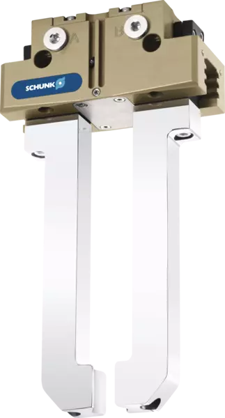
Universal 2-finger parallel gripper with permanent lubrication, high gripping force, and high maximum moments due to the use of a multi-tooth guidance
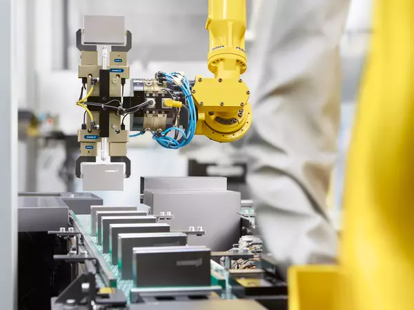
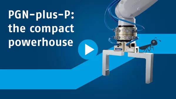
The compact powerhouse
PGN-plus-P for precise gripping under heavy loads.
All values of our PGN-plus-P have been impressing for more than 30 years! As the No. 1 universal gripper, it sets sustainable benchmarks in the market and is synonymous with perfection and versatility.
Your benefits
More performance in a compact space: The PGN-plus-P combines high gripping force, maximum versatility, and the highest level of process reliability for demanding automation tasks. Whether dealing with high cycle rates, varied workpieces, or complex gripping situations – the universal gripper ensures reliable operation and a long service life. It is for very good reason that it has been setting the standard in gripping technology for over 30 years.
How you can benefit
Strong gripping force for heavy working loads
The large piston area provides high gripping forces. This ensures a secure grip – even during demanding tasks and with heavy components.
Suitable for complex gripping situations and workpieces
The multi-tooth slide guidance reliably absorbs high load moments. This enables the use of long gripper fingers while simultaneously ensuring a long service life for the gripper.
The right gripper model for every application
A wide range of options ensures optimal solutions for a wide variety of applications and environmental conditions.
Proven in production
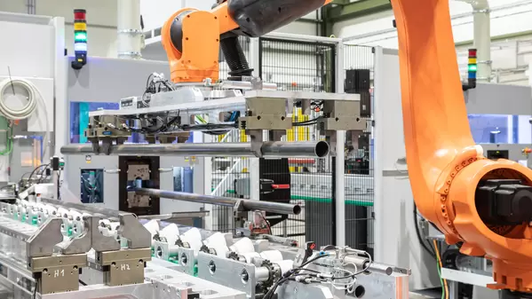
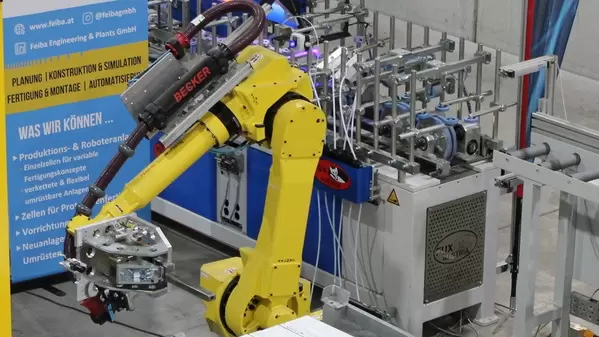
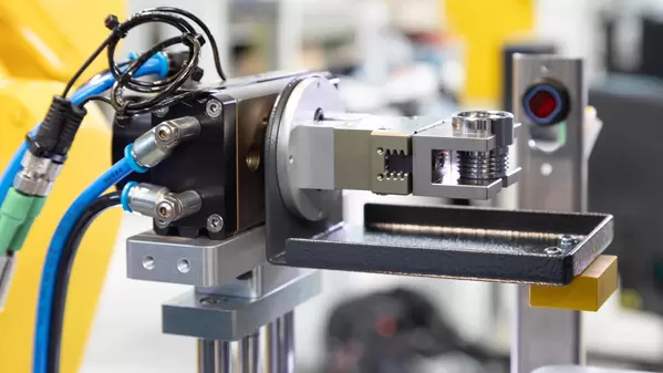
Photo gallery
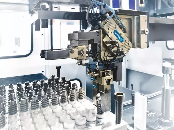
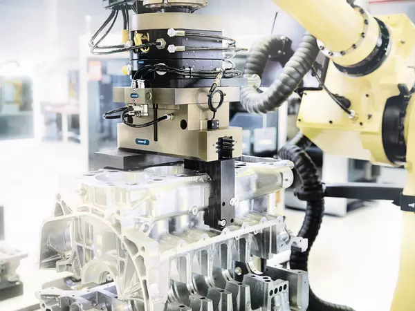
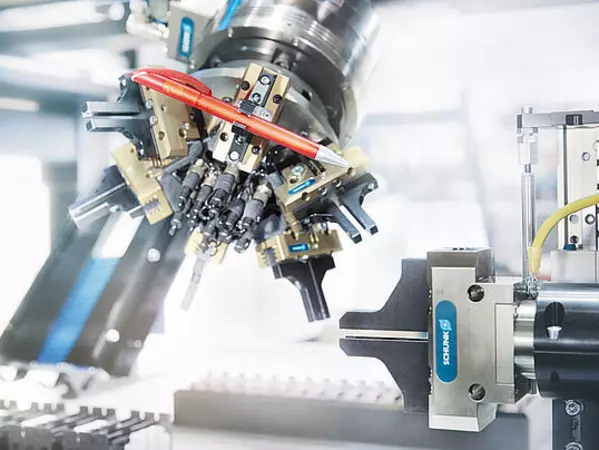
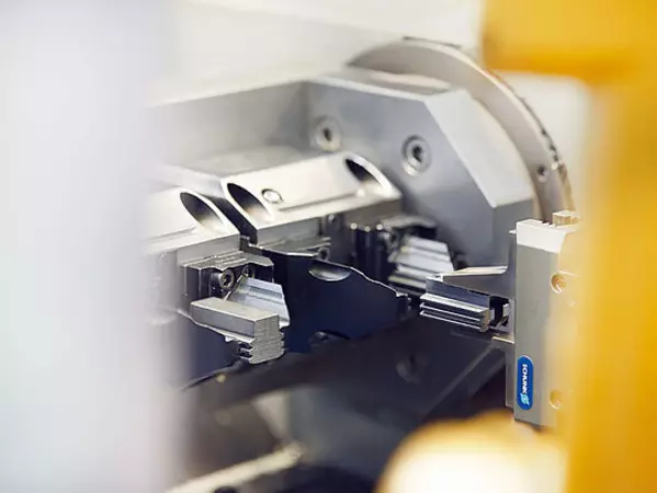
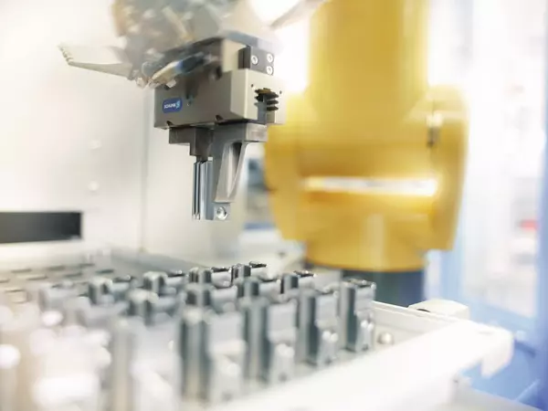
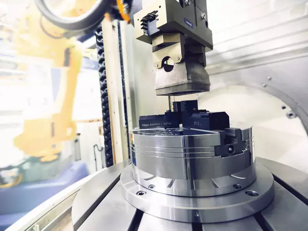
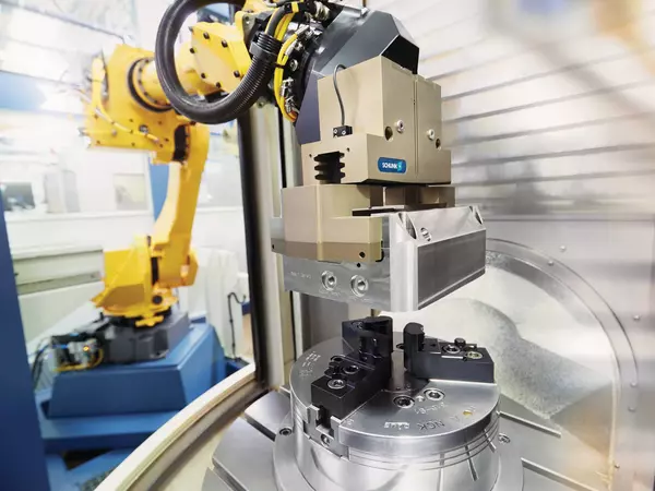
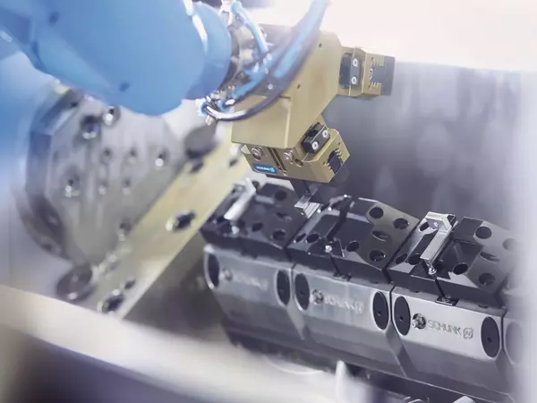
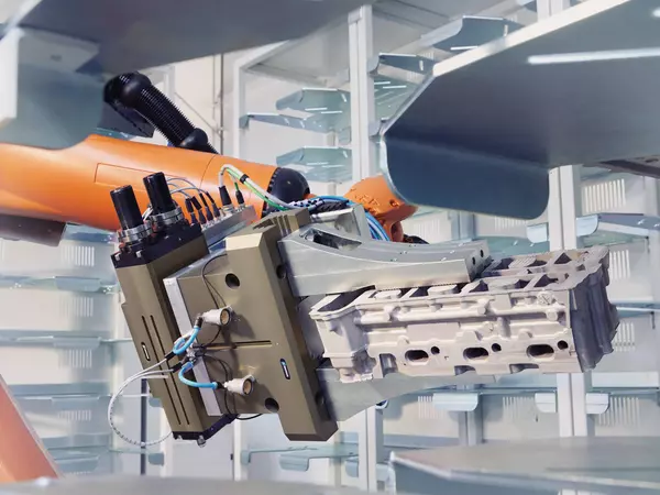
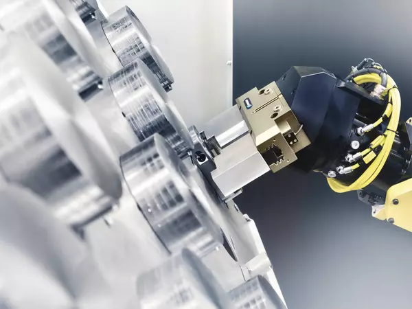
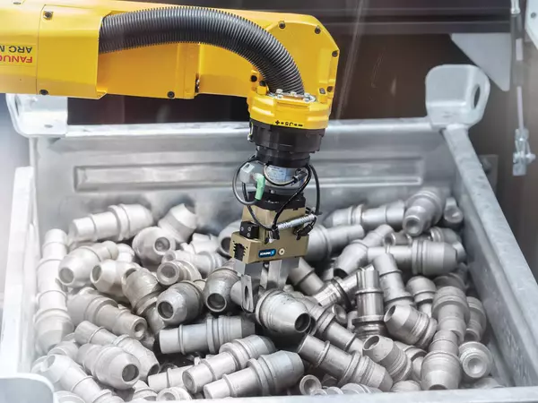
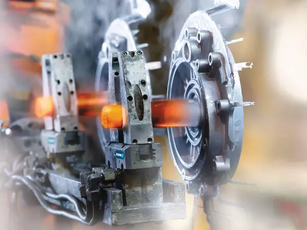
PGN-plus-P superior stories
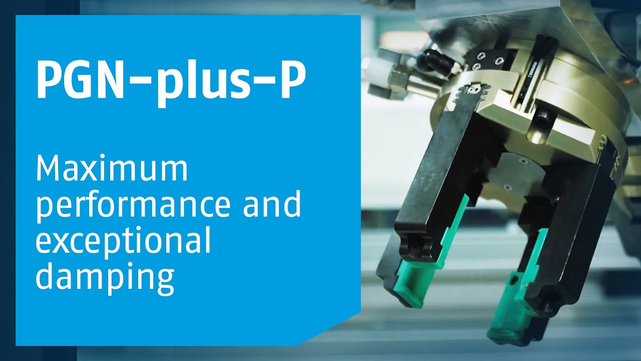
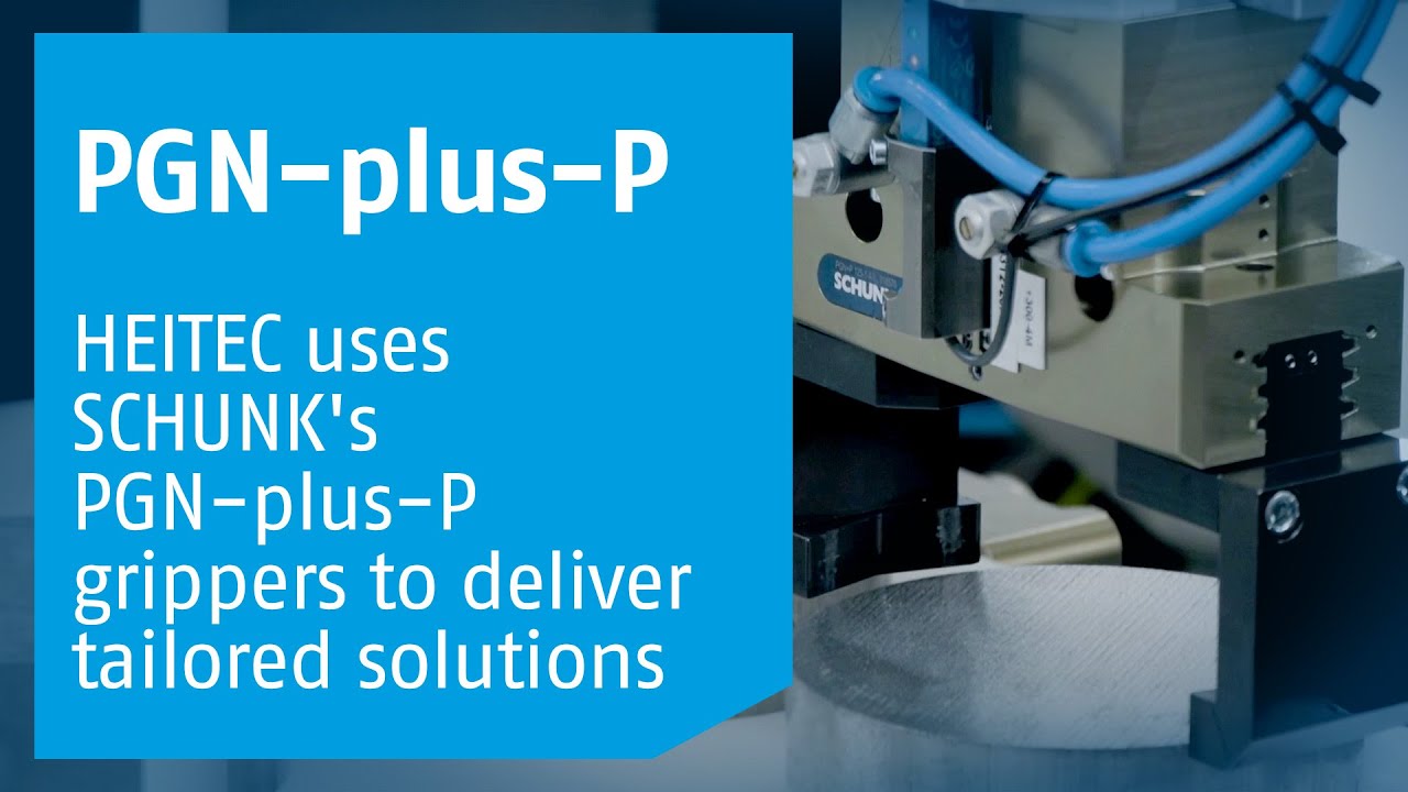
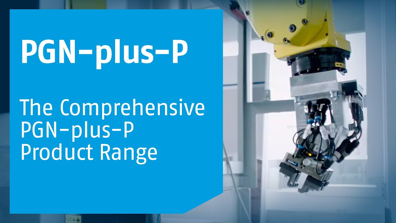
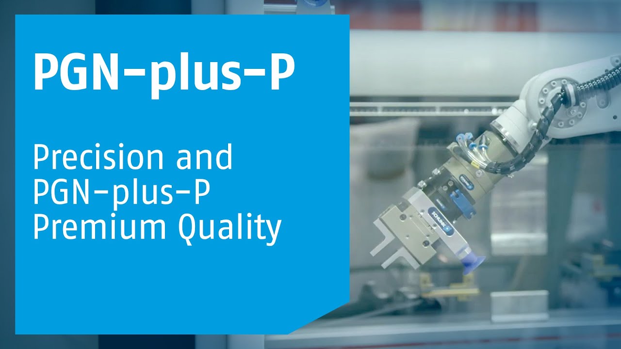
The right standard solution for every requirement
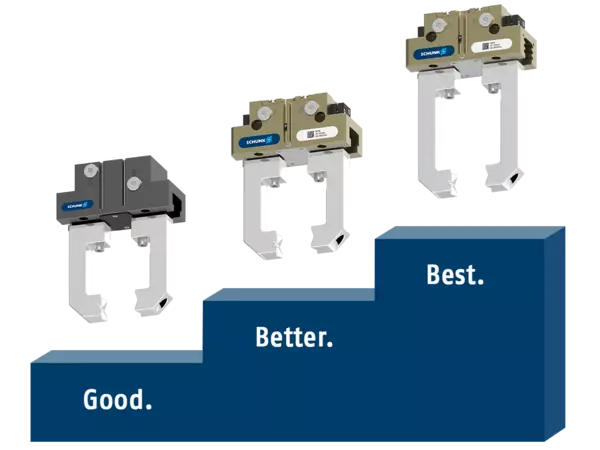
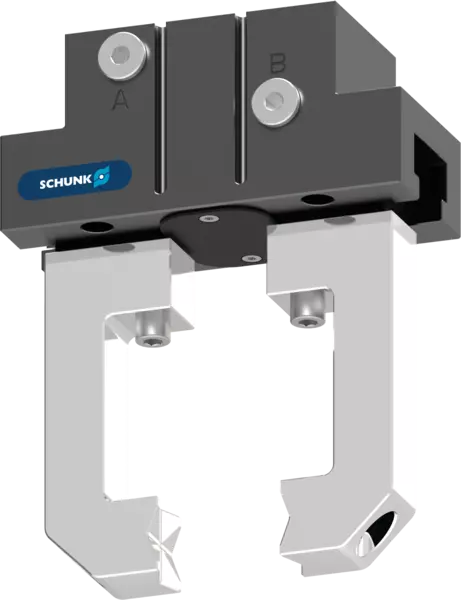
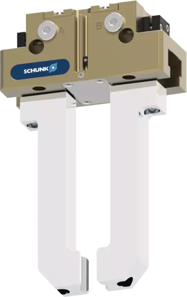
From simple handling to complex automation tasks: SCHUNK offers the right parallel gripper for every requirement. The CGP offers a cost-effective entry point into automation, the JGP-P stands out as a high-performance solution for standard applications, and the PGN-plus-P sets the standard when maximum performance, durability, and flexibility are required.
Forever a benchmark
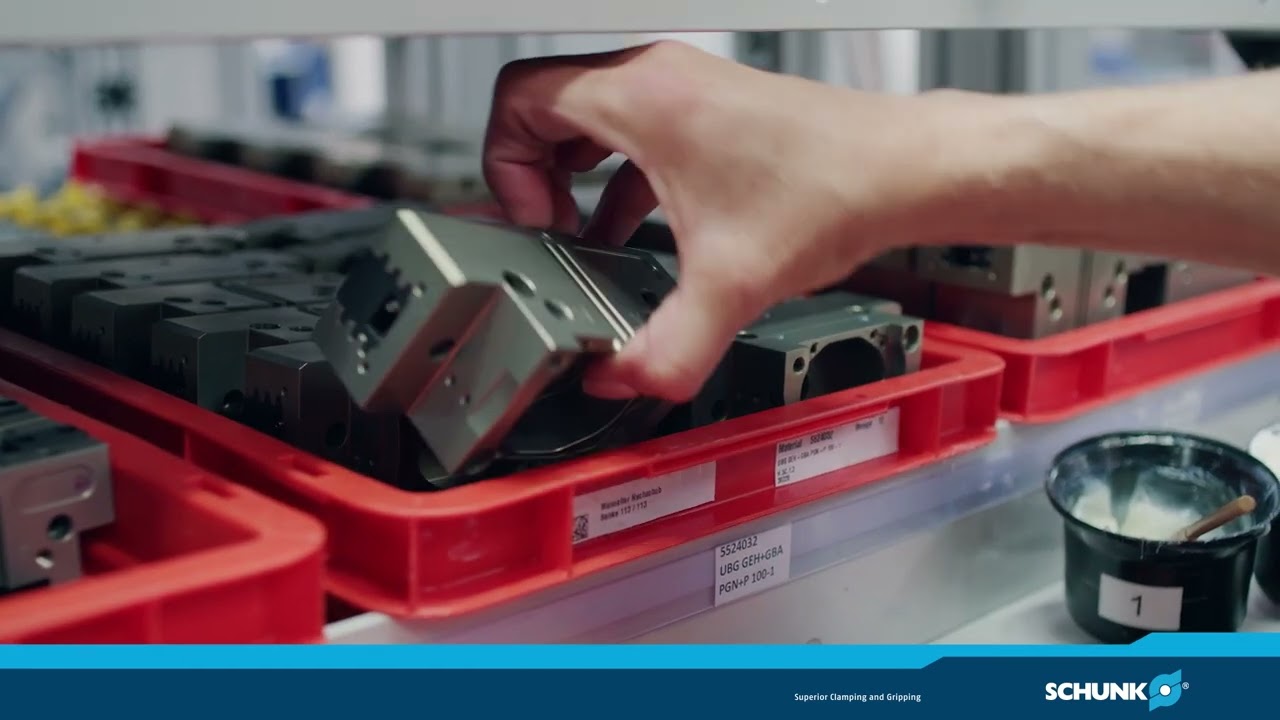
With over 30 years of experience, millions of successful gripping cycles, and continuous innovation, the PGN-plus-P has shaped gripping technology for decades. In our video series, we take a look back at its history and show why it remains one of the most proven universal grippers on the market today.
The foundation for maximum load-bearing capacity
The patented SCHUNK multi-tooth guidance makes the PGN-plus-P particularly high-performance and durable. It enables safe handling of heavy loads, supports the use of longer gripper fingers, and ensures consistently reliable performance. This results in greater flexibility for demanding gripping tasks and higher performance within the same size class.