
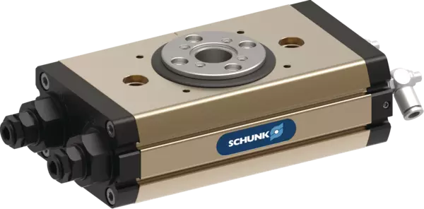
SRM 25-H-180-90-M-6E-SF
ID 1482231
- Angle of rotation: 180 °
- End position adjustability: 90 °
- End position damping: hydr. damper
- Torque: 5.95 Nm
- Number of connectors for feeding through: 6
Détails techniques
| Amortiguación de fin de carrera | amortiguador hidráulico |
|---|---|
| Ángulo de giro [°] | 180 |
| Torque [Nm] | 5.95 |
| Posición central del par [Nm] | 4.7 |
| Número de posiciones intermedias | 1 x M (neumática) |
| Clase de protección IP | 65 |
| Peso [kg] | 3.53 |
| Consumo de fluido (2 x ángulo nominal) [cm³] | 100.0 |
| Presión nominal de servicio [bar] | 6.0 |
| Presión de trabajo mín. [bar] | 4.0 |
| Presión de trabajo máx. [bar] | 6.5 |
| Diámetro del tubo de conexión | 6 x 3.9 x 1.05 |
| Temperatura ambiente mín. [°C] | 5.0 |
| Temperatura ambiente máx. [°C] | 60.0 |
| Normativa para sala blanca ISO 14644-1 | 5 |
| Categoría de sala blanca: ISO 14644-1 | 2015 |
| Precisión de repetición [°] | 0.07 |
| Diámetro del taladro central [mm] | 17.1 |
| Momento de inercia máx. admisible de la masa [kgm²] | 0.16 |
| Momento My máx. [Nm] | 64.0 |
| Máx. fuerza axial Fz máx. [N] | 2250.0 |
| Número de conectores para el paso | 6.0 |
| Tamaño del enchufe (salida) | 4xM8/3-polig2xM8/4-polig |
| Tamaño del conector (accionamiento) | 6xM12/4-polig |
| Número de conductores | 20.0 |
| Tensión máx. [V] | 48.0 |
| Corriente máxima por cable [A] | 1.0 |
| Opción para los sensores de proximidad inductivos | sí |
| Versión con pasos de señal eléctricos | sí |
| Versión para sensores inductivos, fija | sí |
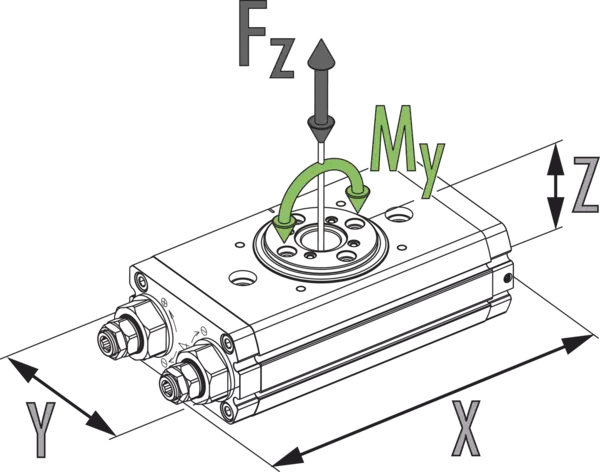
Dimensiones y cargas máximas
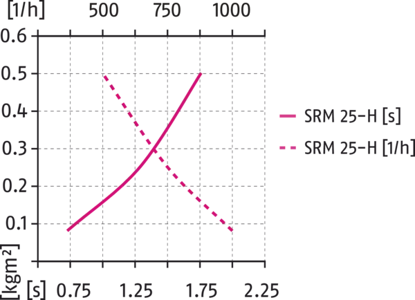
Inercia J* máxima admisible
Dimensiones y cargas máximas
所示力矩和力为静态值,对于基本单元有效,可能会同时出现。必须进行节流,以确保出现旋转动作时不会发生撞击或弹跳现象。否则将缩短使用寿命。
Inercia J* máxima admisible
- Axe X:
- Tiempo de giro
- Axe Y:
- Momento de inercia de la masa
- Axe X supérieur:
- Ciclos por hora
General notes about the series
Repeat accuracy
is defined as a distribution of the end position for 100 consecutive cycles.
Pinion position
is always shown in the left end position. The pinion rotates from here to the right in clockwise direction. The arrow makes the direction of rotation clear.
Pinion screw connection diagram
When setting a swivel angle smaller than 90°, the left end stop must be completely turned in. This means that the left end position has a screw connection diagram on the pinion which is clockwise turned by 90° compared to the main view, which shows a swivel angle of 180°.
Customized angle of rotation
More swivel angles are available on request.
Torque in the end positions
Please note that the final angular degrees (approx. 2°) before the end position can only be approached using the force of a single drive piston. For this reason, double actuated modules only have about half the rated torque available in this area.
Travel to the pneumatic middle position
is carried out using only half of the nominal torque.
Swiveling time
is the rotation time of pinion/flange around the nominal rotation angle. Valve switching times, hose filling times, or PLC reaction times are not included and are to be considered when cycle times are calculated.
Standard conditions
The technical data shown refers to an environment of 20 °C and atmospheric pressure.
Housing material
Aluminum (extruded profile)
Actuation
pneumatic, with filtered compressed air as per ISO 8573-1:2010 [7:4:4].
Operating principle
Double piston rack and pinion principle
Scope of delivery
Swivel unit in the ordered variant, accessory kit (centering sleeves, O-rings for direction connection/detailed contents see operating manual) and safety information. Product-specific instructions can be downloaded at schunk.com/downloads-manuals.
Warranty
24 months
Service life characteristics
on request