Funktion
Sectional diagram
Sectional diagram
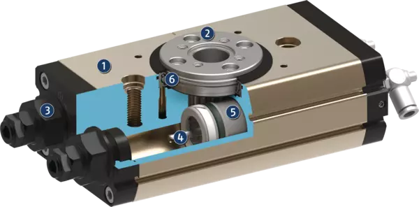
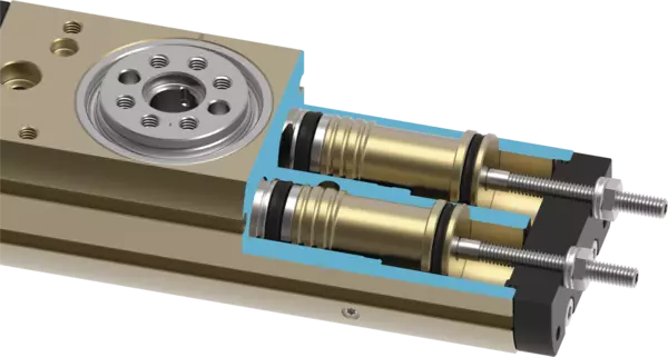
When subjected to pressure, the two pneumatic pistons move their end faces in a straight line in their respective bores thus turning the pinion by means of the serrations on their sides.
- 1
-
Housing
weight-optimized due to the use of hard-anodized aluminum alloy - 2
-
Pinion
stabile pinion for transforming the piston movement into a rotary movement - 3
-
Swivel angle adjustment
for quick, easy and intuitive end position adjustment - 4
-
Damping
Hydraulic shock absorbers for high moments of inertia - 5
-
Drive
Pneumatic, powerful double piston drive - 6
-
Bearing
play-free, pre-loaded bearing
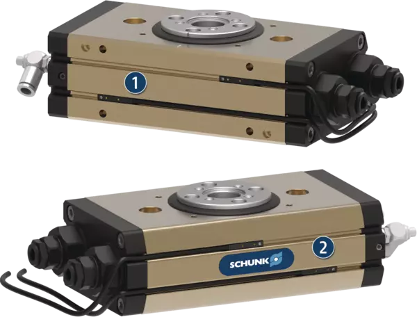
Versions with small end position adjustability
Version with large end position adjustability
Variant with pneumatic center position
Lager van het tandwiel
Ajustement de la position finale et de la course d'amortissement

Version avec amortissement externe
Version avec joint tournant pneumatique
Version avec joint tournant électrique
Monitoring via electronic magnetic switches
Monitoring via inductive proximity sensors and adjustable control cam
Monitoring via inductive proximity sensors and fixed control cam
Versions with small end position adjustability
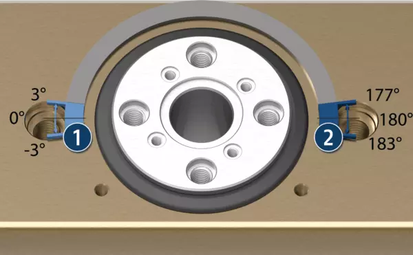
Slight end position adjustability for fine adjustment of both end positions (±3°) in case of swivel units with a swivel angle of 180°
- 1
-
Adjustment range starting angle
- 2
-
Adjustment range end angle
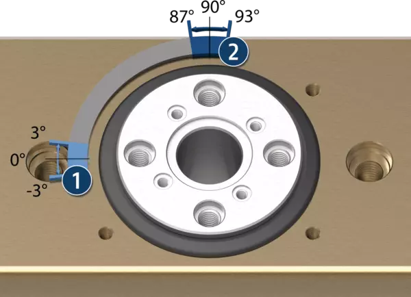
Slight end position adjustability for fine adjustment of both end positions (± 3°) in case of swivel units with a swivel angle of 90°
- 1
-
Adjustment range starting angle
- 2
-
Adjustment range end angle
Version with large end position adjustability
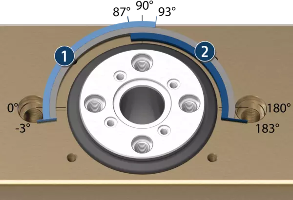
Large end position adjustability for variable adjustment of the swivel angle between 0° and 186°. Both end positions can each be limited by 90° (±3°).
- 1
-
Adjustment range starting angle
- 2
-
Adjustment range end angle
Variant with pneumatic center position
The SRM swivel unit can optionally be ordered with pneumatic center position. This makes it possible, to control a third position in addition to the two end positions.
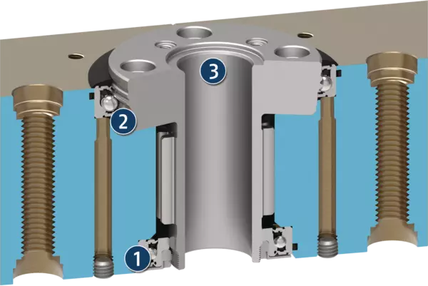
Lager van het tandwiel
Het rondsel van de draaimodule SRM wordt aangedreven door twee zuigers en is op twee punten gelagerd. Het bovenste lager is geïntegreerd in het tandwiel, waardoor een minimale hoogte van de volledige eenheid wordt bereikt. Het onderste lager is spelingvrij voorgespannen, waardoor een zeer hoge nauwkeurigheid en lagerstijfheid wordt bereikt. Beide lagers zijn aan de buitenzijde afgedicht met afdichtingen voorzien van dubbele lip. De afdichtingen zijn vervaardigd van robuust en duurzaam FKM-materiaal.
- 1
-
Palier préchargé à double joints à lèvres
- 2
-
Palier intégré à double joints à lèvres
- 3
-
Grand alésage central pour le passage de câbles et de flexibles
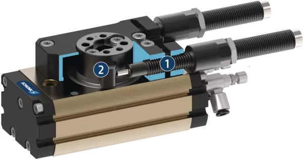
Ajustement de la position finale et de la course d'amortissement
Les deux positions finales et la course d'amortissement peuvent être ajustées manuellement sur l'unité. En raison du préréglage en usine de la course d'amortissement, son réglage n'est pas nécessaire pour de nombreuses applications. Les repères sur le couvercle indiquent le sens de rotation sur l'ajustement de l'angle de rotation
- 1
-
Ajustement de la course d'amortissement
- 2
-
Ajustement de la position finale
Version avec amortissement externe
Dans le modèle de base de la SRM, le mouvement des pistons est amorti par les amortisseurs situés dans la chambre des pistons. Dans le modèle avec amortissement externe, les amortisseurs de chocs sont fixés sur la face côté pignon de l'unité. Le mouvement y est amorti directement sur l'unité de rotation. En conséquence, un moment d'inertie plus élevé et une répétabilité plus grande peuvent être réalisés. De plus, un couple complet est disponible dans toutes les positions.
- 1
-
Amortisseur hydraulique
- 2
-
Unité de rotation avec butée mécanique
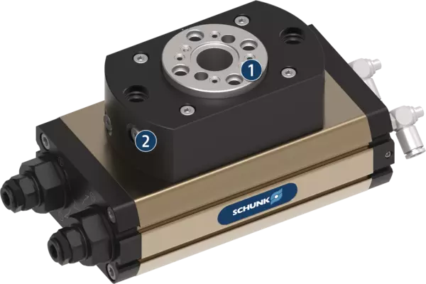
Version avec joint tournant pneumatique
L'unité de rotation SRM peut être équipée en option avec un joint tournant pneumatique permettant un passage fiable d'air comprimé, de gaz, ou de vide. Dans le cas des tailles SRM 10, 12, 14 et 16, le joint tournant utilise l'alésage central, qui n'est donc plus disponible. Dans le cas des tailles SRM 20, 25, 32 et 40, l'alésage central reste complètement intact, même si l'option de join tournant pneumatique est choisie.
- 1
-
Raccordement pour l'élément en rotation, équipé avec joint tournant pneumatique
- 2
-
Raccordement partie fixe du joint tournant pneumatique
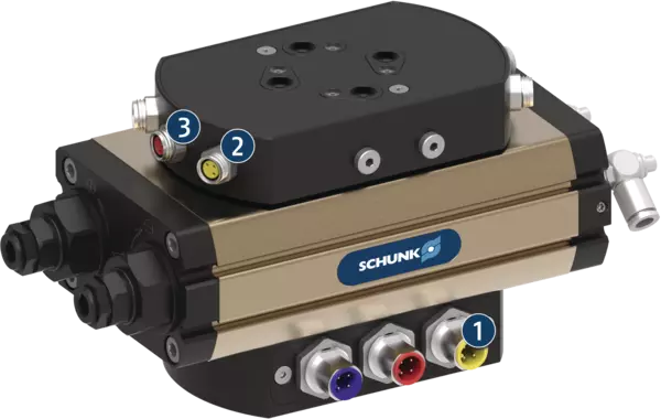
Version avec joint tournant électrique
L'unité de rotation SRM peut être équipée en option d'un joint tournant électrique, ce qui assure une transmission opérationnelle fiable des signaux électriques. Le joint tournant électrique est équipé sur les deux côtés de connecteurs M8 ou M12 standard et avec codage par couleur. Cela simplifie l'identification des signaux et facilite la mise en service.
- 1
-
Plug connector on the driving side, 4-pole, color coded
- 2
-
Plug connector on the driven side, 3-pole, color coded
- 3
-
Plug connector on the driven side, 4-pole, color coded
Monitoring via electronic magnetic switches
There are two C-slots on each side of the SRM swivel unit, into which the SCHUNK electronic magnetic switches MMS can be inserted. This ensures flexible monitoring of the end positions, regardless of the installation position of the SRM.
- 1
-
Monitoring with magnetic switch on the back of the swivel unit
- 2
-
Monitoring with magnetic switch on the front of the swivel unit
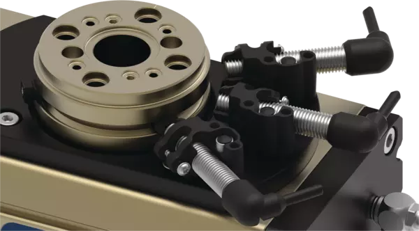
Monitoring via inductive proximity sensors and adjustable control cam
To monitor the end positions of the swivel unit with inductive sensors, an additional set-up is mounted onto the rotary table. For flexible monitoring of individual swivel angles, a version with adjustable control cam is available. This allows up to three positions to be inductively monitored.
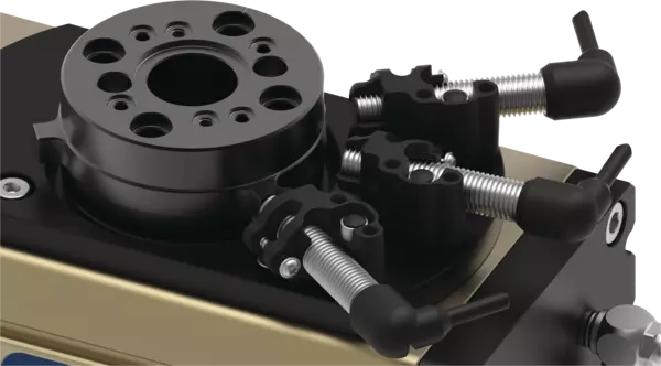
Monitoring via inductive proximity sensors and fixed control cam
For simple commissioning and maintenance of inductive monitoring, a version with a fixed control cam is also available. This is not adjustable and therefore only available for swivel angles of 180° or 90°. As a result, monitoring of up to three positions is possible.
Application example
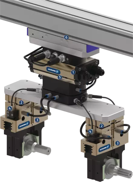
Application example
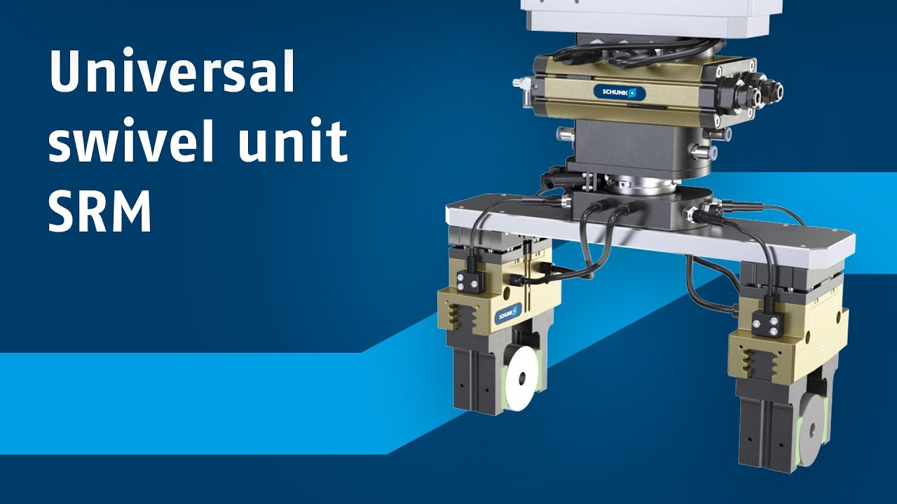
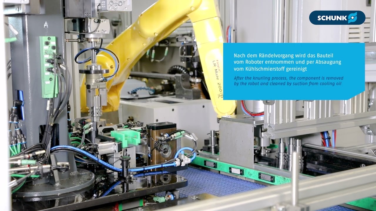
Swivel unit with electrical and pneumatic feed-through and double gripper for loading and unloading a machine tool
- 1
-
Universal rotary actuator SRM
- 2
-
Tolerance compensation unit TCU
- 3
-
Universal gripper PGN-plus-P
- 4
-
Inductive proximity switches IN
- 5
-
Magnetic switch MMS
- 6
-
Universal linear axis Beta with toothed belt drive