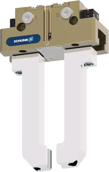
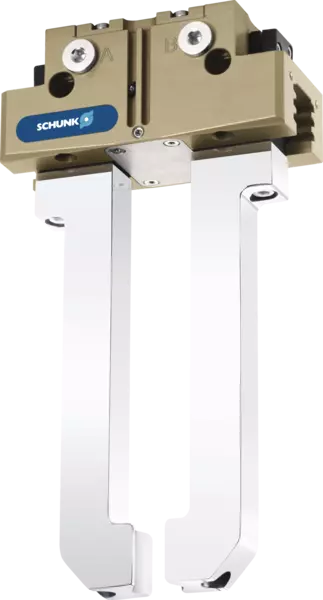

PGN-plus-P
Functie
Funktionsschnittbild
Der Kolben wird über Druckluft nach oben bzw. unten bewegt.
Die schrägen Wirkflächen des Keilhakens erzeugen dabei eine synchrone parallele Backenbewegung.
- 1
-
Vielzahn-Gleitführung
Höchste Lebensdauer durch Schmierstofftaschen in der robusten Vielzahnführung sowie Aufnahme hoher Kräfte und Momente über große Führungsabstützung - 2
-
Grundbacke
mit standardisiertem Anschraubbild zur Adaption der werkstückspezifischen Greiferfinger - 3
-
Halterung für Sensorik
Halterungen für Näherungsschalter und einstellbare Schaltnocken im Gehäuse - 4
-
Gehäuse
ist gewichtsoptimiert durch Verwendung einer hochfesten Aluminiumlegierung - 5
-
Zentrier- und Befestigungsmöglichkeiten
für die universelle Montage des Greifers - 6
-
Wig-haak ontwerp
voor grote krachtoverbrenging en minimale slijtage als gevolg van grotere diagonale trekvlakken - 7
-
Zuiger
Maximale kracht via maximaal oppervlak van aandrijvingszuiger
ATEX-versie EX
Variant voor behoud van grijpkracht AS/IS
Instellingen van de regelnokken tijdens de bewaking met inductieve naderingsschakelaars
Optional mounting possibility under the cover sheet for customer-specific additional structure
Centering and mounting options for gripper assembly
Pneumatic connections for the power supply
Sectional diagram of gripping force maintenance version AS
ATEX-versie EX
De 'stofdichte' optie biedt een betere bescherming tegen binnendringende stoffen.
U kunt de optie naar keuze bestellen als kant-en-klaar gemonteerde grijpervariant of u kunt ze achteraf op de grijper monteren door het pakket "SAD PGN-plus-P" te bestellen.
Variant voor behoud van grijpkracht AS/IS
Het mechanische toestel voor het behoud van de grijpkracht zorgt ervoor dat zelfs bij een drukval een minimale klemkracht wordt toegepast. In de AS-variant zorgt dit voor sluitkracht en in de IS-variant voor openingskracht. De afbeelding geeft de AS-variant weer. Daarnaast kan het toestel voor het behoud van de grijpkracht worden gebruikt om de grijpkracht te verhogen of voor grijpen in één richting.
- 1
-
Tandgeleiding
- 2
-
Basisklem
- 3
-
Beugel voor sensoren
- 4
-
Behuizing
- 5
-
Mogelijkheid tot centreren en monteren
- 6
-
Wig-haak ontwerp
- 7
-
Zuiger
- 8
-
Behoud van grijpkracht
Instellingen van de regelnokken tijdens de bewaking met inductieve naderingsschakelaars
De bewaking met inductieve naderingsschakelaar is standaard mogelijk vanaf bouwgrootte 64. Bij levering zijn de posities "Grijper open" en "Grijper gesloten" ingesteld op de regelnokken. De inductieve sensoren moeten apart worden besteld en worden in de behuizing geschoven tot aan de aanslag en vastgeklemd.
Om andere posities te bewaken, zoals bijv. "werkstuk gegrepen", kunnen beide regelnokken in de betrokken basisklemmen afzonderlijk worden ingesteld.
- 1
-
Control cam preset for "gripper closed" position
- 2
-
Control cam preset for "gripper open" position
- 3
-
Holder with clamping screw for fixing the sensor
- 4
-
Clamping screw for process-reliable fixing of the adjusted switching point
- 5
-
Adjusting screw for setting any switching point
Optional mounting possibility under the cover sheet for customer-specific additional structure
In delivery state, a cover sheet is mounted to the gripper. This can be removed if necessary. Under the cover sheet are threads and fittings for mounting customer-specific designs for implementing additional functions.
- 1
-
Additional centering or support of the workpiece
- 2
-
The cover plate (can be removed)
- 3
-
Ejector with external cylinder attached to the gripper
Centering and mounting options for gripper assembly
The gripper can be installed on two sides and in three screw directions. This allows universal and flexible mounting of the gripper in all conceivable arrangements.
Pneumatic connections for the power supply
The gripper can be flexibly supplied with compressed air on three sides.
- 1
-
At the front via the main air connections A and B by means of air connections and pneumatic hoses. Air purge can be optionally created via S.
- 2
-
At the bottom via direct connections a and b by means of hose-free direct connection. The pneumatic supply is then provided via the adapter plate.
- 3
-
At the rear side via direct connections a and b by means of hose-free direct connection. The pneumatic supply is then via the adapter plate. Air purge can be optionally created via s.
Sectional diagram of gripping force maintenance version AS
- 1
-
Multi-tooth guidance
Maximum service life due to lubricant pockets in the robust multi-tooth guidance, and absorption of high forces and torques by means of the large guidance support - 2
-
Base jaw
with standardized screw connection diagram for the connection of the workpiece-specific gripper fingers - 3
-
Bracket for sensors
Brackets for proximity switches and adjustable control cams in the housing - 4
-
Housing
is weight-optimized due to the use of high-strength aluminum alloy - 5
-
Centering and mounting possibilities
for universal assembly of the gripper - 6
-
Wedge-hook design
for high power transmission and minimal wear as a result of larger diagonal pull surfaces - 7
-
Piston
Maximum force through maximum surface of drive piston - 8
-
Gripping force maintenance
The mechanical gripping force maintenance device ensures that a minimum clamping force will be applied even if there is a drop in pressure.
Application example
Application example
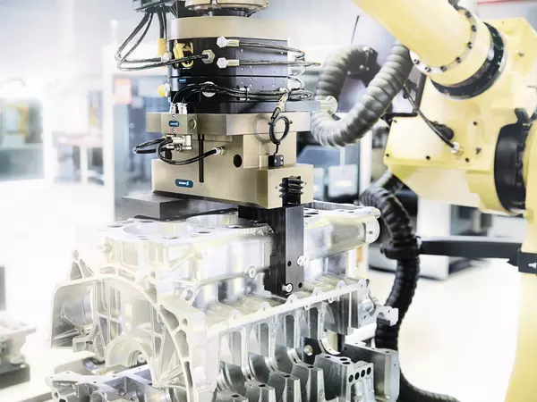
Handling tool for loading and unloading raw and finished parts and compensation of inaccurate position. A sensor distributor is used for routing signals through a cable.
- 1
-
Sensor-Verteiler V4
- 2
-
Toleranzkompensationseinheit TCU-Z
- 3
-
Universalgreifer PGN-plus-P
- 4
-
Sensoren IN
- 5
-
Universalschwenkeinheit SRM