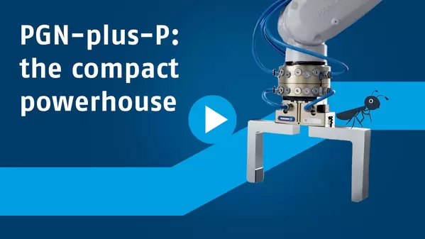
Ver vídeo
PGN-plus-P
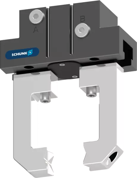
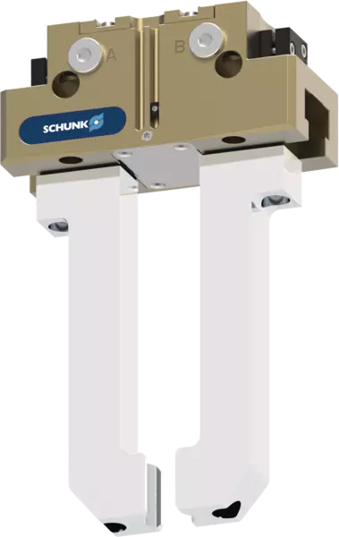
Universal gripper
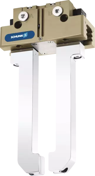
Universal 2-finger parallel gripper with permanent lubrication, high gripping force, and high maximum moments due to the use of a multi-tooth guidance
La carcasa compacta
PGN-plus-P para un agarre preciso con cargas pesadas.
¡Todos los valores de nuestro PGN-plus-P impresionan desde hace más de 30 años! Siendo el gripper universal N.º 1, establece estándares sostenibles en el mercado y es sinónimo de perfección y versatilidad.
La utilidad para usted
Mayor rendimiento en un espacio reducido: La PGN-plus-P combina una gran fuerza de agarre, la máxima versatilidad y el más alto nivel de fiabilidad en el proceso para trabajos de automatización exigentes. Ya sea con ritmos de ciclo elevados, piezas variadas o situaciones de sujeción complejas, la pinza universal garantiza un funcionamiento fiable y una larga vida útil. No en vano lleva más de 30 años marcando la pauta en tecnología de agarre.
Qué ventajas obtiene
Gran fuerza de agarre para cargas de trabajo pesadas
La amplia superficie del émbolo proporciona una gran fuerza de agarre. Esto garantiza un agarre seguro, incluso durante tareas exigentes y con componentes pesados.
Adecuada para situaciones de agarre y piezas complejas
La guía deslizante de dentado múltiple absorbe de forma fiable los momentos de carga elevados. Esto permite utilizar dedos prensores largos y, al mismo tiempo, garantiza una larga vida útil de la pinza.
El modelo de pinza adecuado para cada aplicación
Una amplia gama de opciones garantiza soluciones óptimas para una gran variedad de aplicaciones y condiciones ambientales.
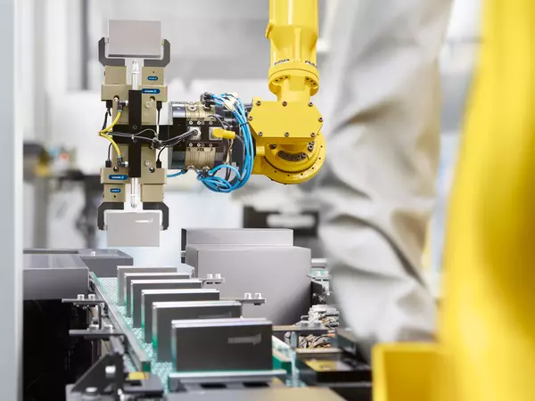
Probado en producción
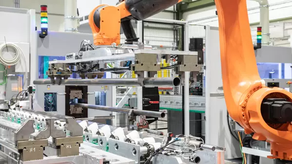
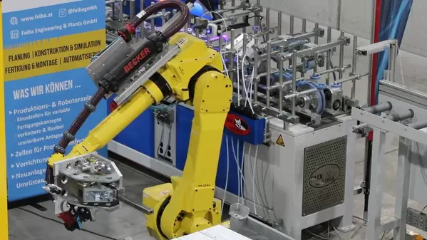
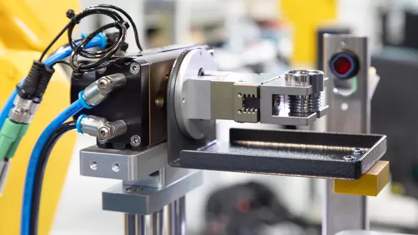
Galería de imágenes
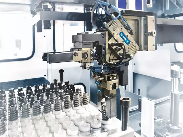
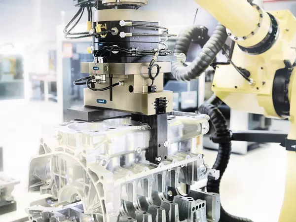
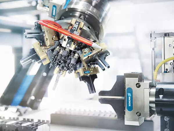
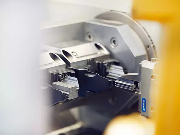
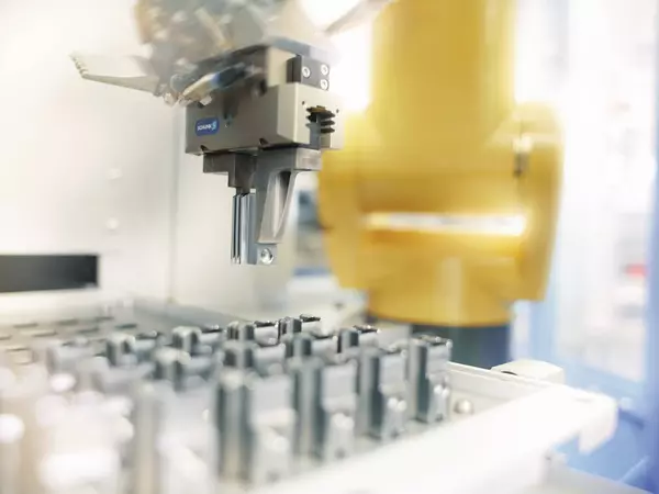
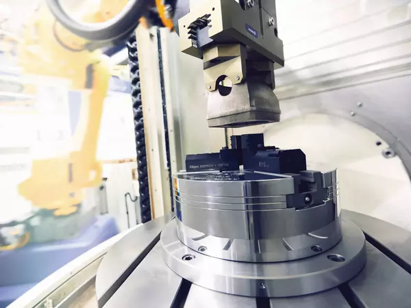
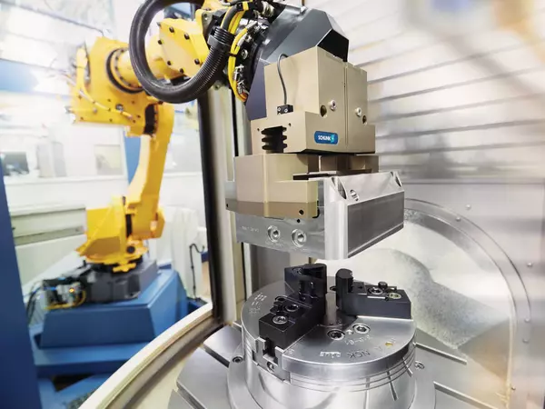
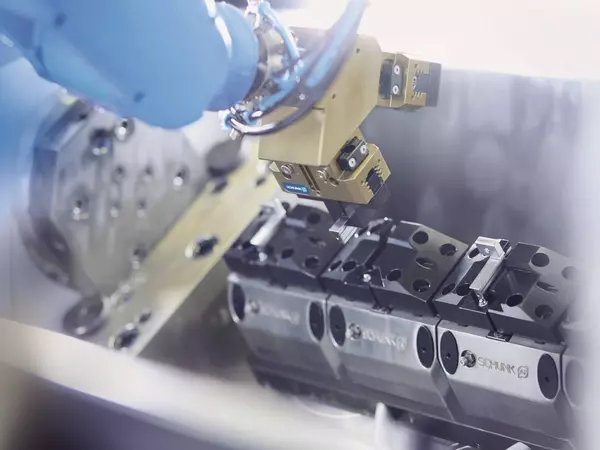
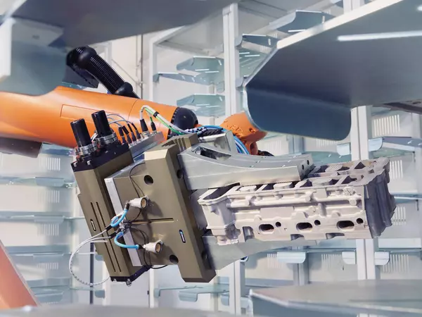
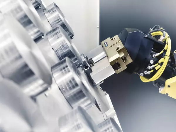
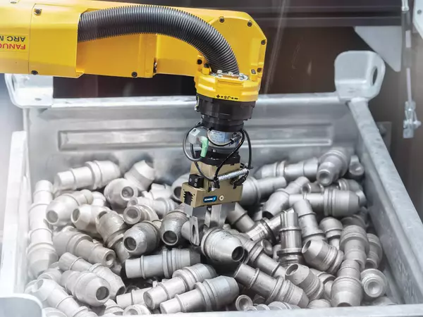
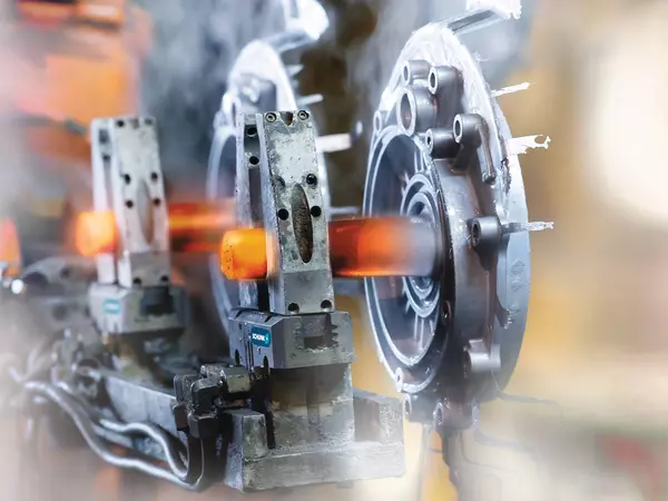
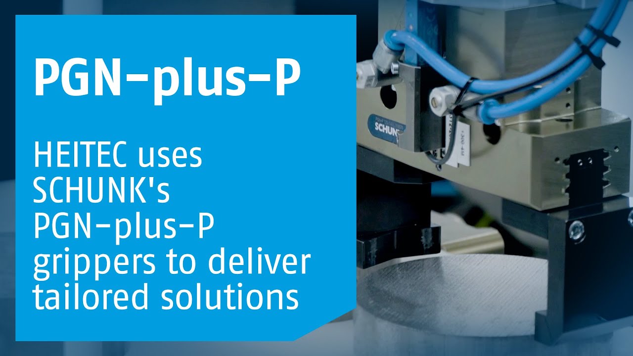
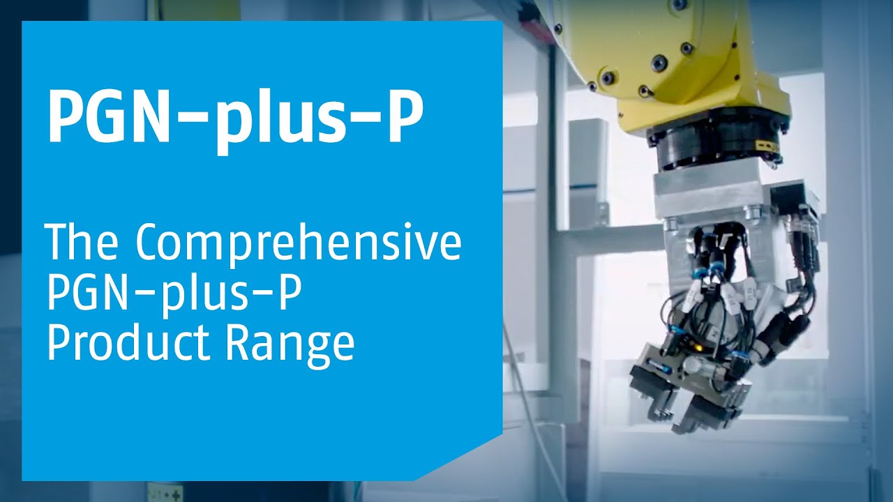
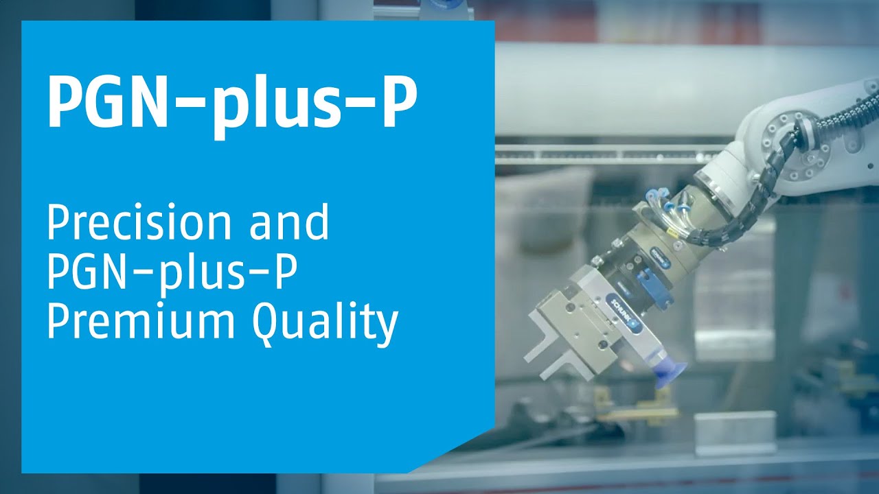
Casos de éxito con PGN-plus-P
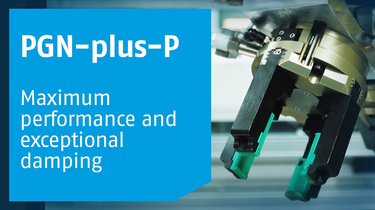
La solución estándar correcta para cualquier requisito
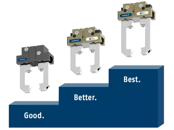
Desde operaciones de manipulación sencillas hasta tareas de automatización complejas: SCHUNK ofrece la pinza paralela adecuada para cada necesidad. La pinza CGP es una opción económica para iniciarse en la automatización; la JGP-P destaca como una solución de alto rendimiento para aplicaciones estándar; y la PGN-plus-P marca la pauta cuando se requiere el máximo rendimiento, durabilidad y flexibilidad.
Nuestra referencia de siempre
Con más de 30 años de experiencia, millones de ciclos de agarre realizados con éxito y una innovación constante, la PGN-plus-P ha marcado el rumbo de la tecnología de agarre durante décadas. En nuestra serie de vídeos, repasamos su historia y mostramos por qué sigue siendo una de las pinzas universales más fiables del mercado actual.
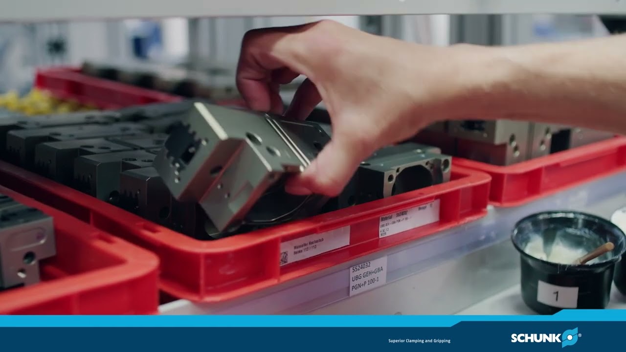
La base para una capacidad de carga máxima
La patentada guía multidentada de SCHUNK confiere a la PGN-plus-P un rendimiento y una durabilidad especialmente elevados. Permite manipular cargas pesadas de forma segura, facilita el uso de dedos prensores más largos, y garantiza un rendimiento fiable en todo momento. Esto se traduce en una mayor flexibilidad para tareas de agarre exigentes y un mayor rendimiento dentro de la misma clase de tamaño.