

Vous trouverez ici un aperçu de nos pinces pneumatiques
Portefeuille de l'alimentation pneumatique


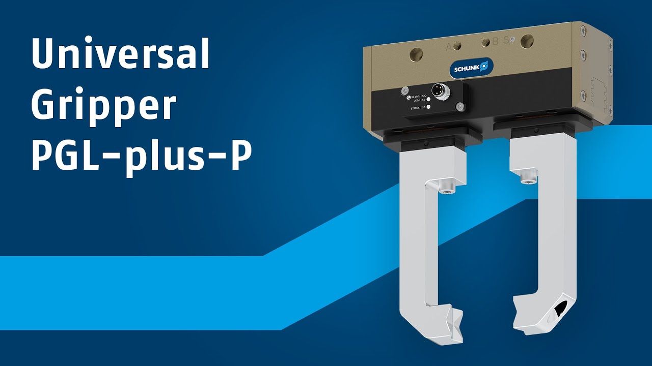
Pour ceux qui recherchent une pince à la fois puissante et polyvalente, la nouvelle PGL-plus-P est le choix idéal. Cette pince universelle pneumatique offre un ensemble de performances uniques en matière de course, de force et de fixation, ce qui la rend parfaitement adaptée aux tâches de manipulation nécessitant de la flexibilité...
La pince universelle pneumatique PGL-plus-P offre une gamme de performances exceptionnelles, en cinq tailles. Grâce à sa longue course de mors de 10 à 25 mm par doigt, les utilisateurs peuvent manipuler une vaste gamme de pièces avec une seule pince.
Avec la PGL-plus-P, vous pouvez augmenter la sécurité de votre application - et élargir la gamme d'utilisations en même temps. Il s'agit de la première pince pneumatique à offrir une maintien de la force de préhension certifié et sécurisé grâce à GripGuard. En cas de perte de pression, au moins 80 % de la force de préhension nominale est maintenue, tandis que les mouvements incontrôlés du mors sont exclus. Cela permet de protéger les opérateurs, d'éviter les pertes de pièces en cas d'urgence ou de dysfonctionnement et d'accroître la sécurité de processus. Cela permet de réduire les efforts et les dépenses nécessaires pour garantir la conformité CE et de réduire l'analyse des risques de l'ensemble de votre système.

La technologie des capteurs IO-Link intégrés augmente les performances de la pince pneumatique et élimine le besoin de capteurs externes, ce qui réduit les coûts d'acquisition, de mise en service et d'entretien. Elle détecte la position du doigt sur toute la course et distingue les pièces avec une grande précision - idéal pour les grandes gammes de pièces. Deux modes de fonctionnement sont disponibles : le mode IO-Link ou le mode SIO. Les modes « Point de préhension » et « Plage de préhension » permettent de programmer les positions de la pièce et de l'outil
de manière simple et rapide.

