
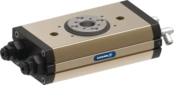
SRM 40-H-180-3-M-SF
ID 1482250
- Angolo di rotazione: 180 °
- Possibilità di regolazione delle posizioni finali: 3 °
- Smorzamento nella posizione finale: Ammortizzatori idraulici
- Coppia: 23.7 Nm
Specifiche tecniche
| Amortecimento da posição final | Ammortizzatori idraulici |
|---|---|
| Ângulo de rotação [°] | 180 |
| Torque [Nm] | 23.7 |
| Posição central de torque [Nm] | 12.5 |
| Número de posições intermediárias | 1 x VM (pneumatico) |
| Classe de proteção IP | 65 |
| Peso [kg] | 8.01 |
| Consumo de fluido (2x nom. ângulo) [cm³] | 380.0 |
| Pressão nominal de operação [bar] | 6.0 |
| Pressão de operação mínima [bar] | 4.0 |
| Pressão máxima de operação [bar] | 6.5 |
| Diâmetro da mangueira de conexão | 8 x 6 x 1 |
| Min. temperatura ambiente [°C] | 5.0 |
| Máx. temperatura ambiente [°C] | 60.0 |
| Classe de sala limpa ISO 14644-1 | 5 |
| Classe de sala limpa: ISO 14644-1 | 2015 |
| Precisão de repetição [°] | 0.05 |
| Diâmetro do furo central [mm] | 26.1 |
| Momento de inércia de massa máx. admissível [kgm²] | 1.49 |
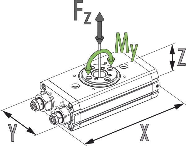
| Momento My máx. [Nm] | 162.0 |
| Força axial máx. Fz máx. [N] | 4000.0 |
| Opção para chaves de proximidade indutivas | Sì |
| Versão para sensores indutivos, fixos | Sì |
Dimensões e cargas máximas
Máx. inércia permitida J*

Dimensões e cargas máximas
Os momentos e forças indicados são valores estáticos, válidos para a unidade base, e podem aparecer simultaneamente. O estrangulamento deve ser feito para garantir que o movimento rotativo ocorra sem impacto ou salto. Caso contrário, a vida útil diminui.
Máx. inércia permitida J*
- Asse X:
- Tempo de rotação
- Asse Y:
- Momento de inércia de massa
- Asse X superiore:
- Ciclos por hora
Notas gerais sobre a série
Precisão de repetição
é definido como uma distribuição da posição final por 100 ciclos consecutivos.
Posição do pinhão
é sempre mostrado na posição final esquerda. O pinhão gira daqui para a direita no sentido horário. A seta deixa claro o sentido de rotação.
Diagrama de conexão do parafuso do pinhão
Ao ajustar um ângulo de rotação menor que 90°, o batente final esquerdo deve ser completamente girado. Isso significa que a posição final esquerda tem um diagrama de conexão do parafuso no pinhão que é girado no sentido horário em 90° em relação à vista principal, que mostra um ângulo de rotação de 180°.
Ângulo de rotação personalizado
Mais ângulos de rotação estão disponíveis mediante solicitação.
Torque nas posições finais
Observe que os graus angulares finais (aprox. 2°) antes da posição final só podem ser aproximados com a força de um único pistão de acionamento. Por esta razão, os módulos de atuação dupla têm apenas cerca de metade do torque nominal disponível nesta área.
Deslocamento para a posição intermediária pneumática
é realizado usando apenas metade do torque nominal.
Tempo de rotação
é o tempo de rotação do pinhão/flange em torno do ângulo de rotação nominal. Os tempos de comutação da válvula, os tempos de enchimento da mangueira ou os tempos de reação do PLC não estão incluídos e devem ser considerados quando os tempos de ciclo são calculados.
Condições padrão
Os dados técnicos apresentados referem-se a um ambiente de 20 °C e pressão atmosférica.
Material da carcaça
Alumínio (perfil extrudado)
Atuação
pneumático, com ar comprimido filtrado conforme ISO 8573-1:2010 [7:4:4].
Princípio de funcionamento
Princípio de pinhão e cremalheira de pistão duplo
Escopo de fornecimento
Unidade giratória na variante encomendada, kit de acessórios (buchas de centralização, O-rings para conexão d/conteúdo de direção-regional, consulte o manual de operação) e informações de segurança. Instruções específicas do produto podem ser baixadas em schunk.com/downloads-manuals.
Garantia
24 meses
Características de vida útil
mediante consulta