

Aquí encontrará un resumen de nuestros grippers neumáticos
Cartera de productos de potencia neumática


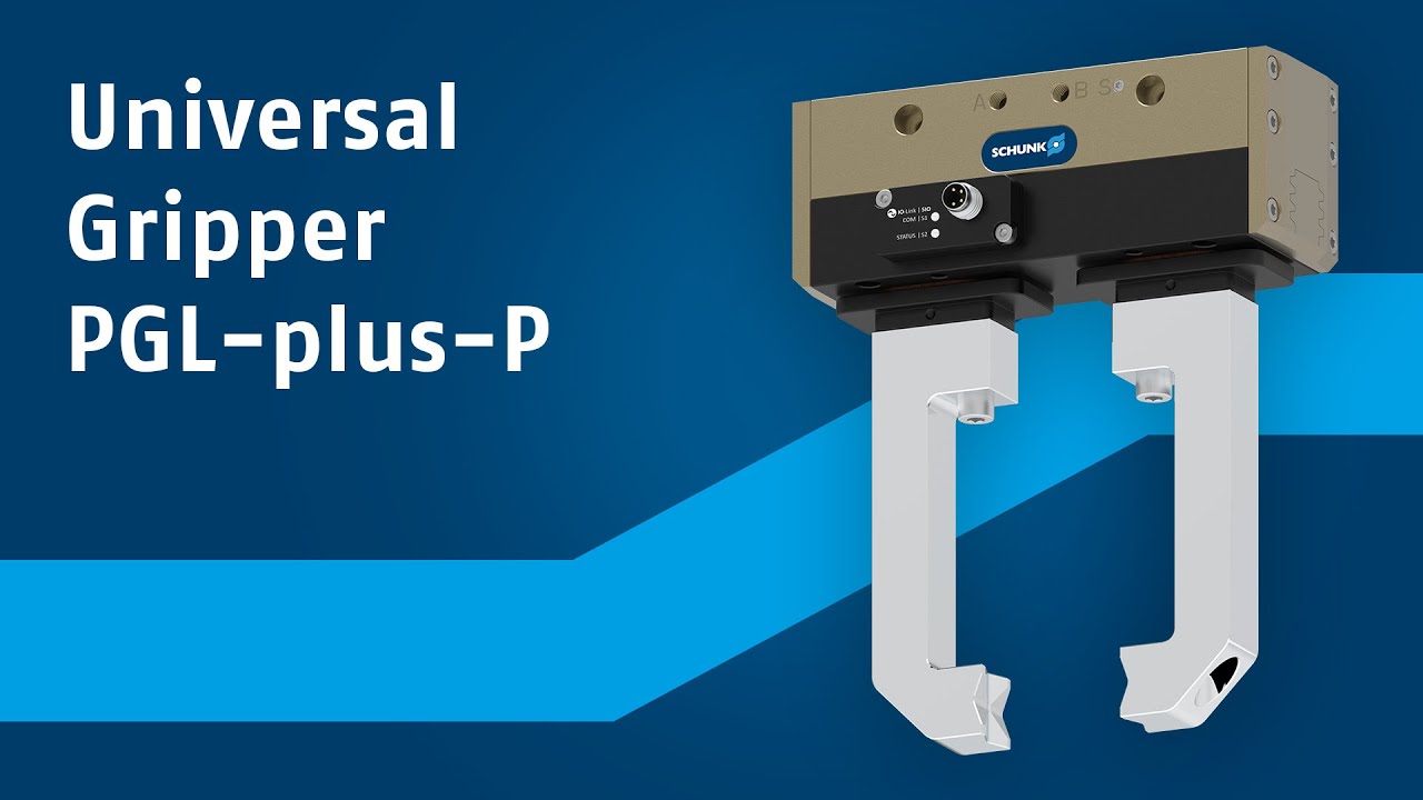
Para aquellos que buscan una pinza potente a la par que versátil, la nueva PGL-plus-P constituye la elección perfecta. El gripper universal neumático ofrece un paquete de prestaciones único de carrera, fuerza y conectividad, lo que sea perfectamente adecuada para tareas de manipulación en las que se requiere flexibilidad...
El gripper neumático universal PGL-plus-P ofrece una gama de prestaciones excepcionales, en cinco tamaños. Gracias a la larga carrera de las mordazas, de 10 a 25 mm por dedo, los usuarios pueden manipular una amplia gama de piezas con tan solo una pinza.
Con el PGL-plus-P, puede aumentar la seguridad de su aplicación y, al mismo tiempo, ampliar la variedad de usos. Es el primer gripper neumático en ofrecer una posición fuerza de agarre segura y certificada con GripGuard. En caso de pérdida de presión, se mantiene al menos el 80 % de la fuerza de agarre nominal, al tiempo que se excluyen los movimientos incontrolados de la mordaza. Esto protege a los operarios, evita pérdidas de piezas en caso de emergencia o avería y aumenta la seguridad del proceso. Esto reduce el esfuerzo y el gasto necesarios para garantizar la conformidad CE y acorta el análisis de riesgos de todo su sistema.

La tecnología de sensores IO-Link integrada aumenta el rendimiento del gripper neumático y elimina la necesidad de sensores externos, lo que a su vez reduce los costes de adquisición, puesta en marcha y mantenimiento. Detecta la posición del dedo a lo largo de toda la carrera y distingue las piezas con gran precisión, lo que resulta ideal para grandes variedades de piezas. Se puede elegir entre dos modos de funcionamiento: IO-Link o modo SIO. Con el modo de punto de agarre y el modo de rango de agarre, puede programar las zonas y
posiciones de las piezas de forma sencilla y rápida.

