JGP-P
Funzionamento
단면도
단면도
피스톤이 압축 에어에 의해 상하로 움직입니다.
쐐기 후크의 각도가 있는 동작면이 동시적인 평행 죠 동작을 만들어냅니다.
- 1
-
T 슬롯 가이드
적재식 견고한 베이스 죠 가이드가 사용되어 매우 긴 그리퍼 핑거 제공 - 2
-
베이스 죠
워크피스별 그리퍼 핑거를 연결하기 위한 표준 나사 연결 도해 - 3
-
센서용 브라켓
근접 스위치 및 하우징 내 조절식 제어 캠용 브라켓 - 4
-
하우징
고강도 알루미늄 합금 사용으로 중량 최적화 - 5
-
센터링 및 설치 가능성
그리퍼 범용 조립용 - 6
-
쐐기 후크 디자인
고전력 전송이 가능하며 넓은 대각선 당김면이 적용되어 마모가 최소화되었습니다 - 7
-
피스톤
최대 구동장치 피스톤 면을 통해 최대의 힘이 전달됩니다.
파지력 유지 버전 AS/IS
유도성 근접 스위치로 모니터링하는 동안 제어 캠 설정
Optional mounting possibility under the cover sheet for customer-specific additional structure
Centering and mounting options for gripper assembly
Pneumatic connections for the power supply
파지력 유지 버전 AS/IS
기계적인 파지력 유지 장치는 압력이 떨어지는 경우에도 최소 고정력이 적용되도록 보장합니다. AS 버전에서는 폐쇄력으로 작용하고 IS 버전에서는 개방력으로 작용합니다. AS 버전을 보여주는 이미지입니다. 파지력 유지 장치를 파지력 강화 또는 1방향 파지에 사용할 수 있습니다.
- 1
-
T 슬롯 가이드
- 2
-
베이스 죠
- 3
-
센서용 브라켓
- 4
-
하우징
- 5
-
센터링 및 설치 가능성
- 6
-
쐐기 후크 디자인
- 7
-
피스톤
- 8
-
파지력 유지
유도성 근접 스위치로 모니터링하는 동안 제어 캠 설정
유도성 근접 스위치를 사용한 모니터링은 64사이즈부터 표준으로 수행할 수 있습니다. 배송 시에는 제어 캠을 사용하여 "그리퍼 열림" 및 "그리퍼 닫힘" 위치가 사전 설정됩니다. 유도 센서는 별도로 주문해야 하며, 하우징 내부로 정지부까지 미끄러져 들어가 클램프로 고정됩니다.
예를 들어, "워크피스 잡음"과 같은 다른 위치를 모니터링하기 위해 두 제어 캠을 각 베이스 죠에 개별적으로 설정할 수 있습니다.
- 1
-
"그리퍼 닫힘" 위치용 제어 캠 사전 설정
- 2
-
Control cam preset for "gripper open" position
- 3
-
Holder with clamping screw for fixing the sensor
- 4
-
Clamping screw for process-reliable fixing of the adjusted switching point
- 5
-
Adjusting screw for setting any switching point
Optional mounting possibility under the cover sheet for customer-specific additional structure
In delivery state, a cover sheet is mounted to the gripper. This can be removed if necessary. Under the cover sheet are threads and fittings for mounting customer-specific designs for implementing additional functions.
- 1
-
Additional centering or support of the workpiece
- 2
-
The cover plate (can be removed)
- 3
-
Ejector with external cylinder attached to the gripper
Centering and mounting options for gripper assembly
The gripper can be installed on two sides and in three screw directions. This allows universal and flexible mounting of the gripper in all conceivable arrangements.
Pneumatic connections for the power supply
The gripper can be flexibly supplied with compressed air on three sides.
- 1
-
At the front via the main air connections A and B by means of air connections and pneumatic hoses. Air purge can be optionally created via S.
- 2
-
At the bottom via direct connections a and b by means of hose-free direct connection. The pneumatic supply is then provided via the adapter plate.
- 3
-
At the rear side via direct connections a and b by means of hose-free direct connection. The pneumatic supply is then via the adapter plate. Air purge can be optionally created via s.
Application example
Application example
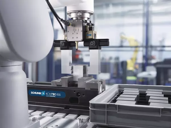
Loading and unloading of a machine tool optimized for the cycle time. By using two grippers on the robot, the machine tool can be loaded automatically in a way that is optimized for the cycle time, and productivity can be increased. After the finished part has been removed from the first gripper, the automated clamping force block is cleaned of coolant and chips via the integrated blow-off nozzle of the double gripper. After that, the second gripper can directly insert the unmachined part and the machining process can be started. The finished part is then deposited and the next unmachined part is picked up again in parallel with the machining of the workpiece.
- 1
-
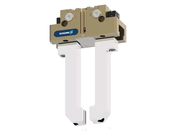
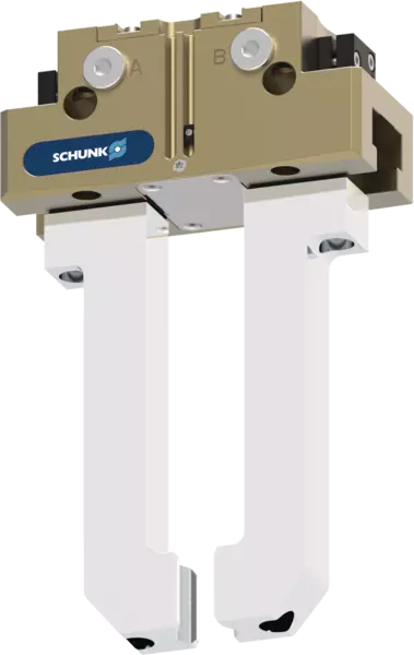
2-finger parallel gripper JGP-P
- 2
-
TANDEM PGS3 clamping force block