
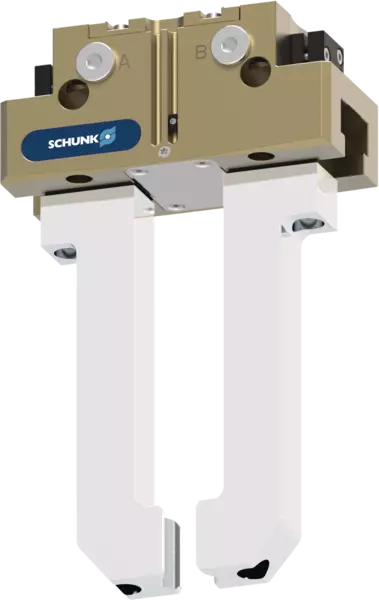
JGP-P
Puesto
Sectional diagram
Sectional diagram
The piston is moved up and down by compressed air.
The angled active surfaces of the wedge-hook produce a synchronized, parallel jaw motion.
- 1
-
T-Nuten-Gleitführung
belastbare, widerstandsfähige Grundbackenführung für große Fingerlängen - 2
-
Grundbacke
mit standardisiertem Anschraubbild zur Adaption der werkstückspezifischen Greiferfinger - 3
-
Halterung für Sensorik
Halterungen für Näherungsschalter und einstellbare Schaltnocken im Gehäuse - 4
-
Gehäuse
ist gewichtsoptimiert durch Verwendung einer hochfesten Aluminiumlegierung - 5
-
Zentrier- und Befestigungsmöglichkeiten
für die universelle Montage des Greifers - 6
-
Keilhakenprinzip
für hohe Kraftübertragung und niedrigsten Verschleiß durch größere Schrägzugfläche - 7
-
Kolben
Maximale Kraft durch maximale Fläche des Antriebkolbens
Greifkrafterhaltungs-Version AS/IS
Ajustes de las levas de mando durante la detección con sensores inductivos-proximidad
Fijación opcional bajo la chapa protectora para estructura adicional específica del cliente
Centering and mounting options for gripper assembly
Pneumatic connections for the power supply
Greifkrafterhaltungs-Version AS/IS
Die mechanische Greifkrafterhaltung stellt auch bei Druckabfall eine Mindestgreifkraft sicher. Diese wirkt bei der AS-Variante als Schließkraft und bei der IS-Variante als Öffnungskraft. Das Bild zeigt die AS-Variante. Die Greifkrafterhaltung lässt sich auch als Greifkrafterhöhung oder für einfach wirkendes Greifen nutzen.
- 1
-
T-Nuten-Gleitführung
- 2
-
Garra base
- 3
-
Soporte para sensores
- 4
-
Carcasa
- 5
-
Opciones de centraje y montaje
- 6
-
Principio de gancho en cuña
- 7
-
Pistones
- 8
-
Mantenimiento de la fuerza de agarre
Ajustes de las levas de mando durante la detección con sensores inductivos-proximidad
La detección con sensor inductivo-proximidad puede llevarse a cabo de serie a partir del tamaño 64. En estado de entrega, las posiciones "pinza abierta" y "pinza cerrada" se preconfiguran con las levas de mando. Los sensores inductivos han de solicitarse por separado y vienen colocados en la carcasa hasta el tope y sujetos.
Para detectar cualquier otra posición, como, por ejemplo, la de "pieza agarrada", ambas levas de mando pueden configurarse de forma individual en las mordazas base correspondientes.
- 1
-
Leva de mando preconfigurada para la posición "pinza cerrada"
- 2
-
Leva de mando preconfigurada para la posición "pinza abierta"
- 3
-
Mandril con tornillo tensor para fijar el sensor
- 4
-
Tornillo tensor para la fijación segura de los puntos de conmutación ajustados
- 5
-
Tornillo de ajuste para configurar cualquier punto de conmutación
Fijación opcional bajo la chapa protectora para estructura adicional específica del cliente
En estado de entrega, se fija una chapa protectora sobre la pinza. Esta puede retirarse cuando sea necesario. Bajo la chapa protectora se encuentran roscas y conectores que sirven para montar los diseños de cada cliente para implementar funciones adicionales.
- 1
-
Soporte o centrado adicional de la pieza
- 2
-
La cubierta (puede retirarse)
- 3
-
Eyector con cilindro externo acoplado a la pinza
Centering and mounting options for gripper assembly
The gripper can be installed on two sides and in three screw directions. This allows universal and flexible mounting of the gripper in all conceivable arrangements.
Pneumatic connections for the power supply
The gripper can be flexibly supplied with compressed air on three sides.
- 1
-
At the front via the main air connections A and B by means of air connections and pneumatic hoses. Air purge can be optionally created via S.
- 2
-
At the bottom via direct connections a and b by means of hose-free direct connection. The pneumatic supply is then provided via the adapter plate.
- 3
-
At the rear side via direct connections a and b by means of hose-free direct connection. The pneumatic supply is then via the adapter plate. Air purge can be optionally created via s.
Application example
Application example
Loading and unloading of a machine tool optimized for the cycle time. By using two grippers on the robot, the machine tool can be loaded automatically in a way that is optimized for the cycle time, and productivity can be increased. After the finished part has been removed from the first gripper, the automated clamping force block is cleaned of coolant and chips via the integrated blow-off nozzle of the double gripper. After that, the second gripper can directly insert the unmachined part and the machining process can be started. The finished part is then deposited and the next unmachined part is picked up again in parallel with the machining of the workpiece.
- 1
-
2-finger parallel gripper JGP-P
- 2
-
TANDEM PGS3 clamping force block