

여기에서 당사의 공압 그리퍼에 대한 개요를 확인하실 수 있습니다.
공압 파워 포트폴리오


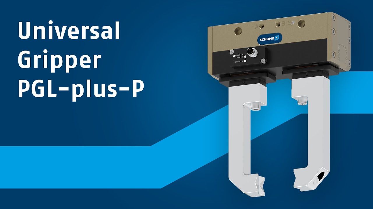
강력하면서도 다재다능한 그리퍼를 찾는 사람들에게, 완벽한 선택을 원한다면 새로운 PGL-plus-P가 있습니다. 공압 범용 그리퍼는 스트로크, 힘, 연결성의 고유한 성능 패키지를 제공하여 유연성이 필요한 작업을 처리하는 데 완전히 적합합니다...
PGL-plus-P 공압 범용 그리퍼는 5가지 크기로 뛰어난 성능을 제공합니다. 핑거당 10~25mm의 대형 죠 스트로크 덕분에 사용자는 하나의 그리퍼로 다양한 부품을 처리할 수 있습니다.
PGL-plus-P를 사용하면 응용 작업의 안전성을 높이고 동시에 사용 범위를 확장할 수 있습니다. GripGuard를 통해 인증된, 안전한 파지력 유지를 제공하는 최초의 공압 그리퍼입니다. 압력 손실이 발생하는 경우 명목상의 그립력의 최소 80%가 유지되며, 통제되지 않는 죠 움직임은 배제됩니다. 이를 통해 작업자를 보호하고, 비상 상황 또는 오작동 시 작업물 손실을 방지하며, 공정 안정성을 높일 수 있습니다. 이를 통해 CE 적합성을 보장하는 데 필요한 노력과 비용이 줄어들고 전체 시스템에 대한 위험 분석도 간소화됩니다.

통합 IO-Link 센서 기술은 공압 그리퍼의 성능을 높이고 외부 센서의 필요성을 없애므로 조달, 시운전 및 서비스 비용이 절감됩니다. 이 제품은 스트로크 전체에 걸쳐 손가락 위치를 감지하고 높은 정밀도로 작업물을 구별합니다. 넓은 부품 범위에 이상적입니다. IO-Link 또는 SIO 모드와 같이 두 가지 작동 모두를 선택할 수 있습니다. "그리핑 포인트 모드" 및 "그리핑 레인지 모드"를 사용하면 작업물 위치와 영역을
간단하고 빠르게 영역을 프로그래밍할 수 있습니다.

