

Zde najdete přehled našich pneumatických chapadel
Portfolio pneumatických pohonů


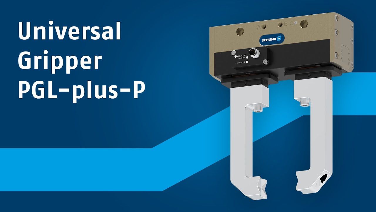
Pro každého, kdo hledá výkonné, ale přesto všestranné chapadlo, je nový PGL-plus-P ideální volbou. Pneumatické univerzální chapadlo nabízí unikátní výkonnostní balíček sestávající ze zdvihu, síly a konektivity, tudíž se dokonale hodí pro manipulační úkoly, kde je vyžadována flexibilita...
Pneumatické univerzální chapadlo PGL-plus-P nabízí výjimečný rozsah výkonu, v pěti velikostech. Díky dlouhému zdvihu čelistí 10 až 25 mm na prst zvládnou uživatelé širokou škálu dílů pouze s jedním chapadlem.
S chapadlem PGL-plus-P můžete zvýšit bezpečnost své aplikace a zároveň rozšířit možnosti použití. Je to první pneumatické chapadlo nabízející certifikované, bezpečné udržování uchopovací síly pomocí GripGuard. V případě ztráty tlaku je udržováno alespoň 80 % jmenovité uchopovací síly, přičemž jsou vyloučeny nekontrolované pohyby čelistí. To chrání obsluhu, zabraňuje ztrátám obrobků v případě nouze nebo poruchy a zvyšuje spolehlivost procesu. Tím se omezuje úsilí a výdaje potřebné k zajištění shody CE a snižuje se analýza rizik celého vašeho systému.

Integrovaná senzorová technologie IO-Link zvyšuje výkon pneumatického chapadla a eliminuje potřebu externích senzorů, což snižuje náklady na pořízení, uvedení do provozu a servis. Zjišťuje polohu prstu po celém zdvihu a s vysokou přesností rozlišuje obrobky - ideální pro široký rozsah dílů. Na výběr jsou dva provozní režimy: IO-Link nebo SIO. Pomocí režimů "Gripping Point Mode" a "Gripping Range Mode" můžete naprogramovat polohy obrobku a
jeho oblasti jednoduše a rychle.

