
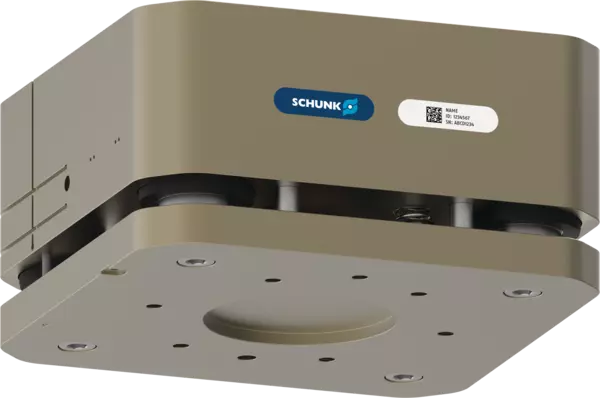
AGM-Z 200
ID 1575995
- Ausgleichsweg Z: 20 mm
- Kraft Fz max.: 11000 N
- Kraft Fd max.: 22000 N
- Max. Federkraft: 1490 N
- Schutzart IP: 50
技術的詳細
| Ausgleichsweg Z [mm] | 20.0 |
|---|---|
| Verriegelungskraft eingefahren [N] | 10500.0 |
| Verriegelungskraft ausgefahren [N] | 13900.0 |
| Min. Federkraft [N] | 930.0 |
| Max. Federkraft [N] | 1490.0 |
| Min. Betriebsdruck [bar] | 2.5 |
| Max. Betriebsdruck [bar] | 6.5 |
| Nennbetriebsdruck [bar] | 6.0 |
| Wiederholgenauigkeit [mm] | 0.02 |
| Anschluss roboterseitig | ISO 9409-1-200-6-M12 |
| Anschluss werkzeugseitig | ISO 9409-1-200-6-M12 |
| Eigenmasse [kg] | 37.5 |
| Min. Umgebungstemperatur [°C] | 5.0 |
| Max. Umgebungstemperatur [°C] | 60.0 |
| Fluidverbrauch [cm³] | 1410.0 |
| Ausfahrzeit [s] | 0.6 |
| Einfahrzeit [s] | 1.1 |
| Luftanschlüsse ver- und entriegelt | G1/8" |
| Max. außermittige Belastung [mm] | 800.0 |
| Schutzart IP | 50 |
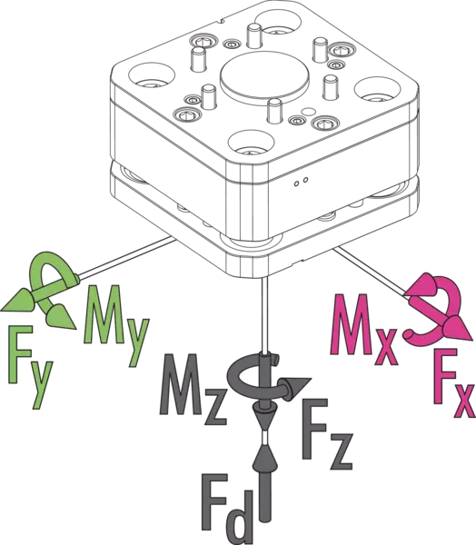
| Max. statisches Moment Mx/My [Nm] | 1600.0 |
| Max. statisches Moment Mz [Nm] | 1800.0 |
| Kraft Fx/Fy max. statisch [N] | 10000.0 |
| Kraft Fz max. statisch [N] | 11000.0 |
| Max. dynamisches Moment Mx/My [Nm] | 800.0 |
| Max. dynamisches Moment Mz [Nm] | 900.0 |
| Kraft Fx max. dynamisch [N] | 3400.0 |
| Kraft Fy max. dynamisch [N] | 3400.0 |
| Kraft Fz max. dynamisch [N] | 5500.0 |
| Max. Kraft Fd [N] | 22000.0 |
Max. Belastungen
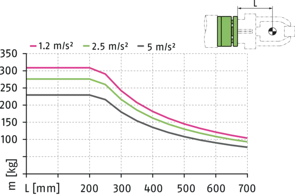
AGM-Z Lastdiagramm - Vertikaler Aufbau

AGM-Z Lastdiagramm - Horizontaler Aufbau
Auslenkung
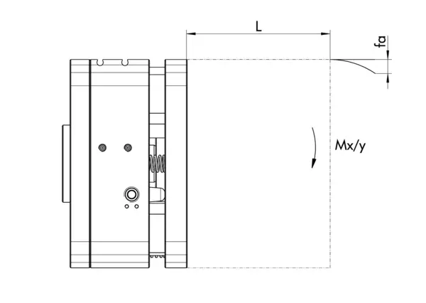
Auslenkungsdiagramm AGM-Z - Horizontaler Aufbau

Max. Belastungen
Es handelt sich hierbei um die Summe aller statischen Belastungen, die auf die Ausgleichseinheit wirken dürfen.
AGM-Z Lastdiagramm - Vertikaler Aufbau
- X 軸:
- Abstand Schwerpunkt
- Y 軸:
- Auslenkung
AGM-Z Lastdiagramm - Horizontaler Aufbau
- X 軸:
- Abstand Schwerpunkt
- Y 軸:
- Auslenkung
Auslenkung
Auslenkungsdiagramm AGM-Z - Horizontaler Aufbau
- X 軸:
- Abstand Schwerpunkt
- Y 軸:
- Auslenkung
General notes about the series
Harsh environmental conditions
Please note that use under harsh environmental conditions (e.g. in the coolant area, cast and grinding dust) can considerably reduce the service life of the units, and we will not take over any warranty. However, in many cases we can find a solution. Please contact us for assistance.
Fluid consumption
refers to the air consumption per one retraction and extension cycle
Guidance system
Ball guides
Monitoring
via magnetic switch or inductive proximity sensor
Actuation
pneumatic, with filtered compressed air as per ISO 8573-1:2010 [7:4:4].
Housing
hard anodized aluminum alloy, functional parts made of hardened steel
Scope of delivery
Compensation unit in the ordered variant, elements for mechanical connection and safety information. Product-specific instructions can be downloaded at schunk.com/downloads-manuals.
Warranty
24 months